Goodnight Bowl

Description

This bowl acts as a night-light and glows red when picked up while it is dark. Upon being set down, it plays “Twinkle, Twinkle Little Star” and the light slowly fades. During the day when there is light, it appears to be just a bowl of cotton balls. In this way, it acts as an object that will put the user to sleep at the end of their day.

I used a force-sensitive resistor on the bottom of the bowl to measure when it is set down, and I used a light sensor on the bowl to measure whether it is dark around the bowl. A piezo speaker plays music.

Materials

  • 1 ceramic bowl
  • 1 force-sensitive resistor
  • masking tape
  • 1 Arduino
  • cotton balls
  • 1 red LED
  • 1 light sensor
  • 1 piezo speaker
  • 1 22 KΩ resistor
  • 3 10 KΩ resistors
  • wires

Images

Goodnight Bowl

Goodnight Bowl

Code

int ledPin = 9; // select the output pin for LED
int speakerPin = 7; // select the output pin for speaker
int lightSensorPin = A0; // select input for light sensor
int forceSensorPin = A2; // select input for force sensor

int forceValue = 0; // variable to store force value
int lightValue = 0; // variable to store light value
int wasHeld = 0; // boolean for if force was very low in last loop

byte names[] = {'c', 'd', 'e', 'f', 'g', 'a', 'b', 'C'};
int tones[] = {1915, 1700, 1519, 1351, 1275, 1136, 1014, 956}; // f was changed to f sharp (370 Hz)
byte melody[] = "7d1p7d1p7a1p7a1p7b1p7b1p8a6a2p7g1p7g1p7f1p7f1p7e1p7e1p8d6d2p";
int count = 0;
int count2 = 0;
int count3 = 0;
int MAX_COUNT = 24;
int LIGHT_THRESHOLD = 200;
int FORCE_THRESHOLD = 100;

void setup() {
// put your setup code here, to run once:
pinMode(speakerPin, OUTPUT);
pinMode(ledPin, OUTPUT);
Serial.begin(9600);
}

void loop() {
int max_subloops;
// put your main code here, to run repeatedly:
lightValue = analogRead(lightSensorPin);
// turn the ledPin on, convert from 0-1023 scale to 0-255
//analogWrite(ledPin, (lightValue - 300) / 4); //forceValue / 4 +

forceValue = analogRead(forceSensorPin);
if (forceValue >= FORCE_THRESHOLD && wasHeld && lightValue < LIGHT_THRESHOLD) { wasHeld = 0; digitalWrite(speakerPin, LOW); max_subloops = sizeof(melody) / 2; for (count = 0; count < max_subloops; count++) { analogWrite(ledPin, 255 * (max_subloops - count - 1) / max_subloops); // 48 converts from byte to int // 30 is length of time for (count3 = 0; count3 <= (melody[count*2] - 48) * 30; count3++) { for (count2=0;count2<8;count2++) { // 8 is the size of names if (names[count2] == melody[count*2 + 1]) { digitalWrite(speakerPin,HIGH); delayMicroseconds(tones[count2]); digitalWrite(speakerPin, LOW); delayMicroseconds(tones[count2]); } if (melody[count*2 + 1] == 'p') { // make a pause of a certain size digitalWrite(speakerPin, 0); delayMicroseconds(500); } } } } } else if (forceValue < FORCE_THRESHOLD) { if (lightValue < LIGHT_THRESHOLD) { digitalWrite(ledPin, HIGH); } wasHeld = 1; } else { wasHeld = 0; } Serial.print(lightValue); Serial.println(); }

Quickening and slowing childhood

Summary

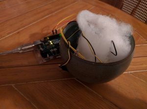
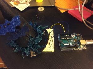
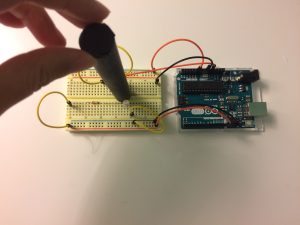
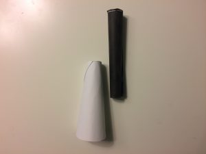
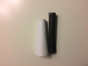
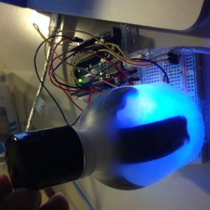
When I first heard the piezo speaker output, I instantly thought of Super Mario Bros. The theme song has a similar tone, and is a game which led me to think of some kind of joystick like the ones used on the old controllers.I cut an old toilet paper tube and attached the speaker and part of a pot to one half, which attaching the turning part of the pot to the other half. By turning the two halves in opposite directions, you can control the tempo of the song.

You can watch the video here!
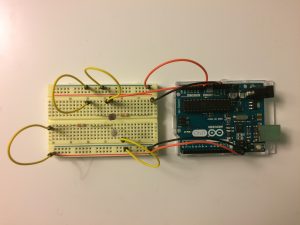

Components

  • Arduino
  • Breadboard
  • 1 potentiometer
  • 1 piezo speaker
  • hookup wires
  • toilet paper roll, scissors, tape

Code

/*
 Arduino Mario Bros Tunes
 With Piezo Buzzer and PWM

 Connect the positive side of the Buzzer to pin 3,
 then the negative side to a 1k ohm resistor. Connect
 the other side of the 1 k ohm resistor to
 ground(GND) pin on the Arduino.

 by: Dipto Pratyaksa
 last updated: 31/3/13
*/

/*************************************************
 * Public Constants
 *************************************************/

#define NOTE_B0 31
#define NOTE_C1 33
#define NOTE_CS1 35
#define NOTE_D1 37
#define NOTE_DS1 39
#define NOTE_E1 41
#define NOTE_F1 44
#define NOTE_FS1 46
#define NOTE_G1 49
#define NOTE_GS1 52
#define NOTE_A1 55
#define NOTE_AS1 58
#define NOTE_B1 62
#define NOTE_C2 65
#define NOTE_CS2 69
#define NOTE_D2 73
#define NOTE_DS2 78
#define NOTE_E2 82
#define NOTE_F2 87
#define NOTE_FS2 93
#define NOTE_G2 98
#define NOTE_GS2 104
#define NOTE_A2 110
#define NOTE_AS2 117
#define NOTE_B2 123
#define NOTE_C3 131
#define NOTE_CS3 139
#define NOTE_D3 147
#define NOTE_DS3 156
#define NOTE_E3 165
#define NOTE_F3 175
#define NOTE_FS3 185
#define NOTE_G3 196
#define NOTE_GS3 208
#define NOTE_A3 220
#define NOTE_AS3 233
#define NOTE_B3 247
#define NOTE_C4 262
#define NOTE_CS4 277
#define NOTE_D4 294
#define NOTE_DS4 311
#define NOTE_E4 330
#define NOTE_F4 349
#define NOTE_FS4 370
#define NOTE_G4 392
#define NOTE_GS4 415
#define NOTE_A4 440
#define NOTE_AS4 466
#define NOTE_B4 494
#define NOTE_C5 523
#define NOTE_CS5 554
#define NOTE_D5 587
#define NOTE_DS5 622
#define NOTE_E5 659
#define NOTE_F5 698
#define NOTE_FS5 740
#define NOTE_G5 784
#define NOTE_GS5 831
#define NOTE_A5 880
#define NOTE_AS5 932
#define NOTE_B5 988
#define NOTE_C6 1047
#define NOTE_CS6 1109
#define NOTE_D6 1175
#define NOTE_DS6 1245
#define NOTE_E6 1319
#define NOTE_F6 1397
#define NOTE_FS6 1480
#define NOTE_G6 1568
#define NOTE_GS6 1661
#define NOTE_A6 1760
#define NOTE_AS6 1865
#define NOTE_B6 1976
#define NOTE_C7 2093
#define NOTE_CS7 2217
#define NOTE_D7 2349
#define NOTE_DS7 2489
#define NOTE_E7 2637
#define NOTE_F7 2794
#define NOTE_FS7 2960
#define NOTE_G7 3136
#define NOTE_GS7 3322
#define NOTE_A7 3520
#define NOTE_AS7 3729
#define NOTE_B7 3951
#define NOTE_C8 4186
#define NOTE_CS8 4435
#define NOTE_D8 4699
#define NOTE_DS8 4978

#define melodyPin 3
//Mario main theme melody
int melody[] = {
 NOTE_E7, NOTE_E7, 0, NOTE_E7,
 0, NOTE_C7, NOTE_E7, 0,
 NOTE_G7, 0, 0, 0,
 NOTE_G6, 0, 0, 0,

 NOTE_C7, 0, 0, NOTE_G6,
 0, 0, NOTE_E6, 0,
 0, NOTE_A6, 0, NOTE_B6,
 0, NOTE_AS6, NOTE_A6, 0,

 NOTE_G6, NOTE_E7, NOTE_G7,
 NOTE_A7, 0, NOTE_F7, NOTE_G7,
 0, NOTE_E7, 0, NOTE_C7,
 NOTE_D7, NOTE_B6, 0, 0,

 NOTE_C7, 0, 0, NOTE_G6,
 0, 0, NOTE_E6, 0,
 0, NOTE_A6, 0, NOTE_B6,
 0, NOTE_AS6, NOTE_A6, 0,

 NOTE_G6, NOTE_E7, NOTE_G7,
 NOTE_A7, 0, NOTE_F7, NOTE_G7,
 0, NOTE_E7, 0, NOTE_C7,
 NOTE_D7, NOTE_B6, 0, 0
};
//Mario main them tempo
int tempoFast[] = {
 12, 12, 12, 12,
 12, 12, 12, 12,
 12, 12, 12, 12,
 12, 12, 12, 12,

 12, 12, 12, 12,
 12, 12, 12, 12,
 12, 12, 12, 12,
 12, 12, 12, 12,

 9, 9, 9,
 12, 12, 12, 12,
 12, 12, 12, 12,
 12, 12, 12, 12,

 12, 12, 12, 12,
 12, 12, 12, 12,
 12, 12, 12, 12,
 12, 12, 12, 12,

 9, 9, 9,
 12, 12, 12, 12,
 12, 12, 12, 12,
 12, 12, 12, 12,
};

int tempoSlow[] = {
 6, 6, 6, 6,
 6, 6, 6, 6,
 6, 6, 6, 6,
 6, 6, 6, 6,

 6, 6, 6, 6,
 6, 6, 6, 6,
 6, 6, 6, 6,
 6, 6, 6, 6,

 4, 4, 4,
 6, 6, 6, 6,
 6, 6, 6, 6,
 6, 6, 6, 6,

 6, 6, 6, 6,
 6, 6, 6, 6,
 6, 6, 6, 6,
 6, 6, 6, 6,

 4, 4, 4,
 6, 6, 6, 6,
 6, 6, 6, 6,
 6, 6, 6, 6,
};


int speaker = 3;
int sensorValue = 0; // variable to store value coming from sensor
int pot = A0;

void setup(void)
{
 Serial.begin(9600);
 pinMode(speaker, OUTPUT);//declare speaker as output
}
void loop()
{
 sensorValue = analogRead(pot);
 Serial.println("ready");
 Serial.println(sensorValue);

 // iterate over the notes of the melody:
 if (sensorValue < 500) {
 Serial.println("slow");
 Serial.println(" 'Mario Theme1'");
 int size = sizeof(melody) / sizeof(int);
 for (int thisNote = 0; thisNote < size; thisNote++) {

 // to calculate the note duration, take one second
 // divided by the note type.
 //e.g. quarter note = 1000 / 4, eighth note = 1000/8, etc.
 int noteDuration = 1000 / tempoFast[thisNote];

 buzz(melodyPin, melody[thisNote], noteDuration);

 // to distinguish the notes, set a minimum time between them.
 // the note's duration + 30% seems to work well:
 int pauseBetweenNotes = noteDuration * 1.30;
 delay(pauseBetweenNotes);

 // stop the tone playing:
 buzz(melodyPin, 0, noteDuration);

 }

 } else {

 Serial.println(" 'Mario Theme2'");
 int size = sizeof(melody) / sizeof(int);
 for (int thisNote = 0; thisNote < size; thisNote++) {

 // to calculate the note duration, take one second
 // divided by the note type.
 //e.g. quarter note = 1000 / 4, eighth note = 1000/8, etc.
 int noteDuration = 1000 / tempoSlow[thisNote];

 buzz(melodyPin, melody[thisNote], noteDuration);

 // to distinguish the notes, set a minimum time between them.
 // the note's duration + 30% seems to work well:
 int pauseBetweenNotes = noteDuration * 1.30;
 delay(pauseBetweenNotes);

 // stop the tone playing:
 buzz(melodyPin, 0, noteDuration);

 }
 }
}

void buzz(int targetPin, long frequency, long length) {
 digitalWrite(13, HIGH);
 long delayValue = 1000000 / frequency / 2; // calculate the delay value between transitions
 //// 1 second's worth of microseconds, divided by the frequency, then split in half since
 //// there are two phases to each cycle
 long numCycles = frequency * length / 1000; // calculate the number of cycles for proper timing
 //// multiply frequency, which is really cycles per second, by the number of seconds to
 //// get the total number of cycles to produce
 for (long i = 0; i < numCycles; i++) { // for the calculated length of time...
 digitalWrite(targetPin, HIGH); // write the buzzer pin high to push out the diaphram
 delayMicroseconds(delayValue); // wait for the calculated delay value
 digitalWrite(targetPin, LOW); // write the buzzer pin low to pull back the diaphram
 delayMicroseconds(delayValue); // wait again or the calculated delay value
 }
 digitalWrite(13, LOW);

}

Lab 5: Reactive Flower

Description

This rose responds to specific interactions. When a bug lands near the bloom, it turns on, pulsing white light. When a face comes near to the leaf (giving CO2), it calmly pulses blue light. And if you try to pick the flower, squeezing the base of the stem with moderate pressure, it flashes red light. At higher pressure, this flashing is accompanied by a blaring warning sound.

Components

  • Arduino
  • Breadboard
  • 2 photosensors
  • 1 force sensitive resistor (FSR)
  • 1 red, 1 blue, and 1 white LED
  • 1 piezo speaker
  • hookup wires
  • paper, straws, tape

Code

/*
controls various inputs and output to an origami flower
By Leah Rosenbaum
*/

int pullSensor = A0; // force sensor at the base of the stem
int bugSensor = A2; // photo sensor for presense of bug on the calyx
int proximitySensor = A1; // photo sensor for proximity of face to leaf

// select the pins for LED output:
int redPin = 11;
int whitePin = 9;
int bluePin = 10;
int piezoPin = 7;

int pullValue = 0; // stores value coming from the pull/force sensor
int bugValue = 0; // stores value coming from the photo/bug sensor
int proximityValue = 0; // stores value coming from the photo/proximity sensor

void setup() {
// declare the ledPin as an OUTPUT:
pinMode(redPin, OUTPUT);
pinMode(bluePin, OUTPUT);
pinMode(whitePin, OUTPUT);
pinMode(piezoPin, OUTPUT);

Serial.begin(9600);
}

void loop() {
digitalWrite(piezoPin, LOW);

pullValue = analogRead(pullSensor); // read the value from the force sensor
bugValue = analogRead(bugSensor); // read the value from the photo/bug sensor
proximityValue = analogRead(proximitySensor); // read in the value from the photo/proximity sensor

Serial.print("pull value:");
Serial.println(pullValue);
Serial.print("bug value:");
Serial.println(bugValue);
Serial.print("proximity value:");
Serial.println(proximityValue);

if ( pullValue > 700) { //if pulling too hard on the stem
allOff();

//flash the red LED and buzz piezo:
digitalWrite(redPin, HIGH); //turn on red LED
buzzPiezo(1000);
delay(25);

digitalWrite(redPin, LOW); //turn off red LED
buzzPiezo(1000);
delay(25);
}
else if (pullValue > 500) { //touching the stem
allOff();

//flash the red LED:
digitalWrite(redPin, HIGH);
delay(150);
digitalWrite(redPin, LOW);
delay(150);
}
else { //minimal force input
if (proximityValue < 800){ //and proximity to leaf
allOff();

//pulse blue:
fadePin(bluePin, 15, 30);
}
else { //minimal proximity input
if (bugValue < 900){
allOff();

//pulse the white LED:
fadePin(whitePin, 5, 30);
}
}
}
delay(500);
}

void buzzPiezo(int delayTime){
for( int i=0; i<250; i++ ) { // play it for 50 cycles
digitalWrite(piezoPin, HIGH);
delayMicroseconds(delayTime);
digitalWrite(piezoPin, LOW);
delayMicroseconds(delayTime);
}
}

void fadePin(char pinName, int fadeStep, int waitTime){
// fade in from min to max in increments of 5 points:
for (int fadeValue = 0 ; fadeValue <= 255; fadeValue += fadeStep) {
analogWrite(pinName, fadeValue);
delay(waitTime); // wait to see the dimming effect
}
for (int fadeValue = 255 ; fadeValue >= 0; fadeValue -= fadeStep) {
analogWrite(pinName, fadeValue);
delay(waitTime); // wait to see the dimming effect
}
}

void allOff(){
digitalWrite(redPin, LOW);
digitalWrite(bluePin, LOW);
digitalWrite(whitePin, LOW);
digitalWrite(piezoPin, LOW);
}

Images

responsive-flower

[Lab05] Music Box ♪೭੧(❛▿❛✿)੭೨♪

Description

When I was little, I loved music boxes, because I thought they were a toy that offered some interaction. Twist the top, and then let the melody play. There was both a visual and an audio output. The ballerina would twist in pirouettes to the tune of the Nutcracker. In this lab, I decided to create my own using a Little Mermaid Theme.

The dolphin can bob back and forth a bit, but when pressed, the melody will speed up faster. If the melody is too distracting, someone can twist the potentiometer to turn down the sound. There is a mix of red and blue light in the bottom layer of the box that blinks to the melody.

Materials

  • Arduino, Breadboard, Jumper Wires
  • Potentiometer, Force Sensitive Resistor, LEDs
  • Daiso Dolphin (Token), Faux shards (Reflecting diffused light)
  • Sponge (Diffuser)
  • Silk Tape
  • Code

    int potPin = A0;
    int ledPin = 13;
    int fsrPin = A1;
    int ledPin2 = 12;
    int speakerOut = 7;
    byte names[] = {'c', 'd', 'e', 'f', 'g', 'a', 'b', 'C'};
    int tones[] = {1915, 1700, 1519, 1432, 1275, 1136, 1014, 956};
    byte melody[] = "2d1p2e1p2f1p5f5p2e1p2f1p2g1p5g5p1p2d1p2e1p2f1p5f8p2e1p2f1p2e1p2f1p2g1p2g1p5g5p2e1p2f1p5g1p2f1p2g1p5f2d1p2f1p2g1p2a1p2a1p4g8p";
    // count length: 1 2 3 4 5 6 7 8 9 0 1 2 3 4 5 6 7 8 9 0 1 2 3 4 5 6 7 8 9 0
    // 10 20 30
    int count = 0;
    int count2 = 0;
    int count3 = 0;
    int MAX_COUNT =62;
    int statePin = LOW;

    void setup() {
    pinMode(ledPin, OUTPUT);
    pinMode(potPin, INPUT);
    pinMode(ledPin2, OUTPUT);
    pinMode(speakerOut, OUTPUT);
    }

    void loop() {
    digitalWrite(speakerOut, LOW);
    for (count = 0; count < MAX_COUNT; count++) { statePin = !statePin; digitalWrite(ledPin, statePin); for (count3 = 0; count3 <= (melody[count*2] - 48) * 30; count3++) { for (count2=0;count2<8;count2++) { if (names[count2] == melody[count*2 + 1]) { digitalWrite(speakerOut,HIGH); delayMicroseconds(tones[count2]); digitalWrite(ledPin,HIGH); digitalWrite(ledPin2, HIGH); //delayMicroseconds(analogRead(potPin)); digitalWrite(speakerOut, LOW); delayMicroseconds(tones[count2]); digitalWrite(ledPin,LOW); digitalWrite(ledPin2, LOW); //delayMicroseconds(analogRead(potPin)); } if (melody[count*2 + 1] == 'p') { // make a pause of a certain size digitalWrite(speakerOut, 0); Serial.println(analogRead(potPin)); delayMicroseconds(analogRead(fsrPin)); } } } } }

    Harry Potter & the Photocell

    For this lab, I chose to incorporate Harry Potter into my project once again. This time, I chose to trigger the Harry Potter theme song when you wave your magic wand over the Sorting Hat. When you do, the main song from the movie will play from the hat.

    Components:

    1. 1 Arduino Board
    2. 1 Bread board
    3. 1 Piezo speaker
    4. 4 wires
    5. 1 photocell
    6. 1 USB cord
    7. 1 Sorting Hat


    Code:

    /*
     Melody
    
     Plays a melody
    
     circuit:
     * 8-ohm speaker on digital pin 8
    
     created 21 Jan 2010
     modified 30 Aug 2011
     by Tom Igoe
    
    This example code is in the public domain.
    
     http://www.arduino.cc/en/Tutorial/Tone
    
     */
    
    /*************************************************
     * Public Constants
     *************************************************/
    
    #define NOTE_B0 31
    #define NOTE_C1 33
    #define NOTE_CS1 35
    #define NOTE_D1 37
    #define NOTE_DS1 39
    #define NOTE_E1 41
    #define NOTE_F1 44
    #define NOTE_FS1 46
    #define NOTE_G1 49
    #define NOTE_GS1 52
    #define NOTE_A1 55
    #define NOTE_AS1 58
    #define NOTE_B1 62
    #define NOTE_C2 65
    #define NOTE_CS2 69
    #define NOTE_D2 73
    #define NOTE_DS2 78
    #define NOTE_E2 82
    #define NOTE_F2 87
    #define NOTE_FS2 93
    #define NOTE_G2 98
    #define NOTE_GS2 104
    #define NOTE_A2 110
    #define NOTE_AS2 117
    #define NOTE_B2 123
    #define NOTE_C3 131
    #define NOTE_CS3 139
    #define NOTE_D3 147
    #define NOTE_DS3 156
    #define NOTE_E3 165
    #define NOTE_F3 175
    #define NOTE_FS3 185
    #define NOTE_G3 196
    #define NOTE_GS3 208
    #define NOTE_A3 220
    #define NOTE_AS3 233
    #define NOTE_B3 247
    #define NOTE_C4 262
    #define NOTE_CS4 277
    #define NOTE_D4 294
    #define NOTE_DS4 311
    #define NOTE_E4 330
    #define NOTE_F4 349
    #define NOTE_FS4 370
    #define NOTE_G4 392
    #define NOTE_GS4 415
    #define NOTE_A4 440
    #define NOTE_AS4 466
    #define NOTE_B4 494
    #define NOTE_C5 523
    #define NOTE_CS5 554
    #define NOTE_D5 587
    #define NOTE_DS5 622
    #define NOTE_E5 659
    #define NOTE_F5 698
    #define NOTE_FS5 740
    #define NOTE_G5 784
    #define NOTE_GS5 831
    #define NOTE_A5 880
    #define NOTE_AS5 932
    #define NOTE_B5 988
    #define NOTE_C6 1047
    #define NOTE_CS6 1109
    #define NOTE_D6 1175
    #define NOTE_DS6 1245
    #define NOTE_E6 1319
    #define NOTE_F6 1397
    #define NOTE_FS6 1480
    #define NOTE_G6 1568
    #define NOTE_GS6 1661
    #define NOTE_A6 1760
    #define NOTE_AS6 1865
    #define NOTE_B6 1976
    #define NOTE_C7 2093
    #define NOTE_CS7 2217
    #define NOTE_D7 2349
    #define NOTE_DS7 2489
    #define NOTE_E7 2637
    #define NOTE_F7 2794
    #define NOTE_FS7 2960
    #define NOTE_G7 3136
    #define NOTE_GS7 3322
    #define NOTE_A7 3520
    #define NOTE_AS7 3729
    #define NOTE_B7 3951
    #define NOTE_C8 4186
    #define NOTE_CS8 4435
    #define NOTE_D8 4699
    #define NOTE_DS8 4978
    
    int potPin = 0;
    int val = 0;
    int speakerPin = 7;
    
    
    void setup() {
     pinMode(speakerPin, OUTPUT); 
     Serial.begin(9600);
     Serial.println("ready");
    
    }
    
    void loop() {
     digitalWrite(speakerPin, LOW); 
     val = analogRead(potPin); // read value from the sensor
     Serial.println(val);
    
     if (val > 750) {
     tone(speakerPin, 493.88, 1000/3);
     delay(1000/3);
     
     tone(speakerPin, 659.25, 1500/3);
     delay(1500/3);
     tone(speakerPin, 783.99, 500/3);
     delay(500/3);
     tone(speakerPin, 739.99, 1000/3);
     delay(1000/3);
     
     tone(speakerPin, 659.25, 2000/3);
     delay(2000/3);
     tone(speakerPin, 987.77, 1000/3);
     delay(1000/3);
     
     tone(speakerPin, 880.00, 3000/3);
     delay(3000/3);
     
     tone(speakerPin, 739.99, 3000/3);
     delay(3000/3);
     
     tone(speakerPin, 659.25, 1500/3);
     delay(1500/3);
     tone(speakerPin, 783.99, 500/3);
     delay(500/3);
     tone(speakerPin, 739.99, 1000/3);
     delay(1000/3);
     
     tone(speakerPin, 622.25, 2000/3);
     delay(2000/3);
     tone(speakerPin, 698.46, 1000/3);
     delay(1000/3);
     
     tone(speakerPin, 493.88, 5000/3);
     delay(5000/3);
     tone(speakerPin, 493.88, 1000/3);
     delay(1000/3);
     
     tone(speakerPin, 659.25, 1500/3);
     delay(1500/3);
     tone(speakerPin, 783.99, 500/3);
     delay(500/3);
     tone(speakerPin, 739.99, 1000/3);
     delay(1000/3);
     
     tone(speakerPin, 659.25, 2000/3);
     delay(2000/3);
     tone(speakerPin, 987.77, 1000/3);
     delay(1000/3);
     
     tone(speakerPin, 1174.66, 2000/3);
     delay(2000/3);
     tone(speakerPin, 1108.73, 1000/3);
     delay(1000/3);
     
     tone(speakerPin, 1046.50, 2000/3);
     delay(2000/3);
     tone(speakerPin, 830.61, 1000/3);
     delay(1000/3);
     
     tone(speakerPin, 1046.50, 1500/3);
     delay(1500/3);
     tone(speakerPin, 987.77, 500/3);
     delay(500/3);
     tone(speakerPin, 932.33, 1000/3);
     delay(1000/3);
     
     tone(speakerPin, 466.16, 2000/3);
     delay(2000/3);
     tone(speakerPin, 783.99, 1000/3);
     delay(1000/3);
     
     tone(speakerPin, 659.25, 5000/3);
     delay(5000/3);
     tone(speakerPin, 783.99, 1000/3);
     delay(1000/3);
     
     tone(speakerPin, 987.77, 2000/3);
     delay(2000/3);
     tone(speakerPin, 783.99, 1000/3);
     delay(1000/3);
     
     tone(speakerPin, 987.77, 2000/3);
     delay(2000/3);
     tone(speakerPin, 783.99, 1000/3);
     delay(1000/3);
     
     tone(speakerPin, 1046.50, 2000/3);
     delay(2000/3);
     tone(speakerPin, 987.77, 1000/3);
     delay(1000/3);
     
     tone(speakerPin, 932.33, 2000/3);
     delay(2000/3);
     tone(speakerPin, 739.99, 1000/3);
     delay(1000/3);
     
     tone(speakerPin, 783.99, 1500/3);
     delay(1500/3);
     tone(speakerPin, 987.77, 500/3);
     delay(500/3);
     tone(speakerPin, 932.33, 1000/3);
     delay(1000/3);
     
     tone(speakerPin, 466.16, 2000/3);
     delay(2000/3);
     tone(speakerPin, 493.88, 1000/3);
     delay(1000/3);
     
     tone(speakerPin, 987.77, 5000/3);
     delay(5000/3);
     tone(speakerPin, 783.99, 1000/3);
     delay(1000/3);
     
     tone(speakerPin, 987.77, 2000/3);
     delay(2000/3);
     tone(speakerPin, 783.99, 1000/3);
     delay(1000/3);
     
     tone(speakerPin, 987.77, 2000/3);
     delay(2000/3);
     tone(speakerPin, 783.99, 1000/3);
     delay(1000/3);
     
     tone(speakerPin, 1174.66, 2000/3);
     delay(2000/3);
     tone(speakerPin, 1108.73, 1000/3);
     delay(1000/3);
     
     tone(speakerPin, 1046.50, 2000/3);
     delay(2000/3);
     tone(speakerPin, 830.61, 1000/3);
     delay(1000/3);
     
     tone(speakerPin, 1046.50, 1500/3);
     delay(1500/3);
     tone(speakerPin, 987.77, 500/3);
     delay(500/3);
     tone(speakerPin, 932.33, 1000/3);
     delay(1000/3);
     
     tone(speakerPin, 466.16, 2000/3);
     delay(2000/3);
     tone(speakerPin, 783.99, 1000/3);
     delay(1000/3);
     
     tone(speakerPin, 659.25, 5000/3);
     delay(5000/3);
    
     } 
    
     
    }


    Sorting Hat

    Arduino Lamp Photocell Serial Control with Bottle Cork

    Description

    I’m interested in how to push certain part of a system to create changing outputs over the time. With this in mind, for this project, I tried to mimic a serial lighting input environment for the photocell sensor, by making a paper bottle cork which is long enough to cover the photocell entirely inside. In this way, if I push and pull the hollow bottle cork, it can cover the photocell from the outside lighting from 100% to 0%. However, since white paper is actually semi-translucent to light, so I decide to use black paper to make the bottle cork, which is designed to be an excellent shading barrier for the photocell.

    Components

    • 1 paper diffuser
    • 1 black bottle cork
    • Arduino uno
    • wires
    • 1 LED
    • 1 photocell
    • 2 resistors
    • 1 laptop


    Code

    int sensorPin = A0; 
    int ledPin = 13; 
    int sensorValue = 0; 
    
    void setup() {
     // declare the ledPin as an OUTPUT:
     pinMode(ledPin, OUTPUT);
    }
    
    void loop() {
     // read the value from the sensor:
     sensorValue = analogRead(sensorPin);
     // turn the ledPin on
     digitalWrite(ledPin, HIGH);
     // stop the program for <sensorValue> milliseconds:
     delay(sensorValue*5);
     // turn the ledPin off:
     digitalWrite(ledPin, LOW);
     // stop the program for for <sensorValue> milliseconds:
     delay(sensorValue*5);
    }


    Video


    Photos

    img_0910 img_0911 img_0914 img_0915


    Enchanted bottle

    Description

    When the cap of a bottle is screwed on, the bottle is not enchanted. But, when the lid of the bottle is unscrewed, the contents inside the bottle light up and change different colors!

    Materials

    • 3 LEDs (Red, Green, Blue)
    • 3 220k ohm resistors
    • 1 potentiometer
    • 1 diffuser
    • 1 arduino uno
    • 1 breadboard

    Code

    /*
    
     * Code Adapted From:
    
     http://www.arduino.cc/en/Tutorial/AnalogInput
    
     */
    
    int sensorPin = A0; // select the input pin for the potentiometer
    int greenLedPin = 11; // select the pin for the LED
    int blueLedPin = 10;
    int redLedPin = 9;
    int sensorValue = 0; // variable to store the value coming from the sensor
    
    
    int potPin = A1; // Analog input pin that the potentiometer is attached to
    int potValue = 0; // value read from the pot
    int led = 9; // PWM pin that the LED is on. n.b. PWM 0 is on digital pin 9
    int i = 1; //to drive the movement through the lights
    int valueGreen = 125;
    int valueRed = 75;
    int valueBlue =125;
    
    void setup() {
     // declare the ledPin as an OUTPUT:
     pinMode(greenLedPin, OUTPUT);
     pinMode(redLedPin, OUTPUT);
     pinMode(blueLedPin, OUTPUT);
    
     // initialize serial communications at 9600 bps:
     Serial.begin(9600);
     // declare the led pin as an output:
    // pinMode(led, OUTPUT);
    }
    
    void loop() {
     // read the value from the sensor:
     sensorValue = analogRead(sensorPin);
     Serial.println(sensorValue);
     // turn the ledPin on
     if (sensorValue > 375) {
     analogWrite(greenLedPin, 0);
     analogWrite(redLedPin, 0);
     analogWrite(blueLedPin, 0);
     }
     else {
     analogWrite(greenLedPin, valueGreen);
     analogWrite(redLedPin, valueRed);
     analogWrite(blueLedPin, valueBlue);
     valueGreen += i;
     if (valueGreen == 255) {
     i = -i;
     }
     if (valueGreen == 125) {
     i = -i;
     }
     delay(20);
     }
    }


    img_7382

    House from Up

    Description:

    I decided to channel energy from the Disney movie Up. I programmed the piezo to output the theme song from the movie when someone steps on the doorstep of the house. Let’s pretend the house is up in the sky, per the cotton of cloud beneath it. :}

    Components Used:

    • 1 Arduino
    • 1 Resistor (10kΩ)
    • 1 Breadboard
    • 1 piezo
    • 1 FSR potentiometer
    • 1 3D printed house (out of PLA)
    • cotton (to simulate a cloud)

    Code:

    /* Play Melody
     * -----------
     *
     * Program to play melodies stored in an array, it requires to know
     * about timing issues and about how to play tones.
     *
     * The calculation of the tones is made following the mathematical
     * operation:
     *
     * timeHigh = 1/(2 * toneFrequency) = period / 2
     *
     * where the different tones are described as in the table:
     *
     * note frequency period PW (timeHigh) 
     * c 261 Hz 3830 1915 
     * d 294 Hz 3400 1700 
     * e 329 Hz 3038 1519 
     * f 349 Hz 2864 1432 
     * g 392 Hz 2550 1275 
     * a 440 Hz 2272 1136 
     * b 493 Hz 2028 1014 
     * C 523 Hz 1912 956
     *
     * (cleft) 2005 D. Cuartielles for K3
     */
    
    int ledPin = 13;
    int potPin = A0;
    int speakerOut = 7; 
    //byte names[] = {'c', 'd', 'e', 'f', 'g', 'a', 'b', 'C'}; 
    //int tones[] = {1915, 1700, 1519, 1432, 1275, 1136, 1014, 956};
    
    byte names[] ={ 'c', 'd', 'e', 'f', 'g', 'a', 'b', 'C', 'D', 'E', 'F', 'G', 'A', 'B'}; 
    unsigned int tones[] = { 1915, 1700, 1519, 1432, 1275, 1136, 1014, 956, 852, 759, 716, 639, 568, 506};
    
    byte melody[] = "3F3A3F9E5p3F3A3F5E2p3D3F3D4C2p3D8A8G1p3D8A8G1p3D1p9D8p";
    
    int val = 0;
    int count = 0;
    int count2 = 0;
    int count3 = 0;
    int MAX_COUNT = 28;
    int statePin = LOW;
    
    void setup() {
    // pinMode(ledPin, OUTPUT); 
     pinMode(speakerOut, OUTPUT);
    }
    
    void loop() {
     digitalWrite(speakerOut, LOW);
     val = analogRead(potPin); // read value from the sensor
    if (val > 0 ){ 
     for (count = 0; count < MAX_COUNT; count++) {
     statePin = !statePin;
     digitalWrite(ledPin, statePin);
     for (count3 = 0; count3 <= (melody[count*2] - 48) * 30; count3++) {
     for (count2=0;count2<15;count2++) {
     if (names[count2] == melody[count*2 + 1]) { 
     digitalWrite(speakerOut,HIGH);
     delayMicroseconds(tones[count2]);
     digitalWrite(speakerOut, LOW);
     delayMicroseconds(tones[count2]);
     } 
     if (melody[count*2 + 1] == 'p') {
     // make a pause of a certain size
     digitalWrite(speakerOut, 0);
     delayMicroseconds(500);
     }
     }
     }
     }
    }
    }


    Up Melody

    Lab 04

    Description

    I used Arduino with force sensor. I edited the sample process sketch code to turn on the circle into squares with changing color and changing the corners with round angles via force sensor interaction. With different value detected by the force sensor, the color and the size of the square will change as well as the degree of angles of its corners. Lastly, I  uploaded the code and took pictures of the result.

    Components

    • 1 Arduino
    • 3 LED
    • 3 Resistor (220Ω)
    • 1 Breadboard
    • One force sensor

    Code

    /* PROCESSING SKETCH
     * Arduino Ball Paint
     * (Arduino Ball, modified 2008)
     * ---------------------- 
     *
     * Draw a ball on the screen whose size is
     * determined by serial input from Arduino.
     *
     * Created 21 September 2016
     * Noura Howell
     * Edited by Owen Hsiao on Sep. 23 2016
     */
    
    
    import processing.serial.*;
    // Change this to the portname your Arduino board
    String portname = "COM3"; // or "COM5"
    Serial port;
    String buf="";
    int cr = 13; // ASCII return == 13
    int lf = 10; // ASCII linefeed == 10
    
    int serialVal = 0;
    
    int n = serialVal + int(random(10));
    
    
    void setup() {
     size(300,300);
     frameRate(10);
     smooth();
     background(40,40,40);
     noStroke();
     port = new Serial(this, portname, 9600); 
    }
    
    void draw() {
     // erase the screen
     background(40, 40, 40);
    
    // draw the ball
     fill(255, serialVal, 255/n);
     //ellipse(150,150,serialVal,serialVal);
     rect(70, 70, serialVal+30, serialVal +30, serialVal/20);
    }
    
    // called whenever serial data arrives
    void serialEvent(Serial p) {
     int c = port.read();
     if (c != lf && c != cr) {
     buf += char(c);
     }
     if (c == lf) {
     serialVal = int(buf);
     println("val="+serialVal); 
     buf = ""; 
     }
    }


    Lab 4 FSR, Bouncy Balls, Music, and Color

    Description

    Video

    I made a bouncy balls animation where the FSR can control the gravity of the bouncy balls. I’ve attached a youtube video. Music is accompanied with the bouncy ball experienced. Also I added features that will let users control the color of the balls through mouse and control the color of backgrounds through keyboards. The user can also control the spring of the balls through up and down keys.

    I didn’t focus as much on the mechanical part of the lab because I spent too much time playing with the animation and digging into the tutorial. Right now, I’m just controlling the force through my hands. But I definitely had a lot of fun playing with this lab and am looking forward to apply some mechanical concepts in the future.

    Processing Code

    import processing.serial.*;
    import processing.sound.*;
    SoundFile file;

    // Change this to the portname your Arduino board
    String portname = "/dev/cu.usbmodem1421"; // or "COM5"
    Serial port;
    String buf="";
    int cr = 13; // ASCII return == 13
    int lf = 10; // ASCII linefeed == 10
    int SerialVal = 0;
    float r = 0;
    float g = 0;
    float b = 0;

    int numBalls = 40;
    float spring = 0.05;
    float gravity = 0.03;
    float friction = -0.9;
    Ball[] balls = new Ball[numBalls];

    int barWidth = 5;
    int lastBar = -1;

    void setup() {
    size(800, 800);
    for (int i = 0; i < numBalls; i++) { balls[i] = new Ball(random(width), random(height), random(30, 70), i, balls); } noStroke(); file = new SoundFile(this, "spaceBeat.wav"); file.play(); port = new Serial(this, portname, 9600); } void draw() { background(r, g ,b); for (Ball ball : balls) { ball.collide(); ball.move(); ball.display(); } if (keyPressed == true && keyCode == UP) { spring += 0.01; } else if (keyPressed == true && keyCode == DOWN) { spring -= 0.01; } else if (keyPressed == true && key == 'r') { r += 10; } else if (keyPressed == true && key == 'R') { r -= 10; } else if (keyPressed == true && key == 'g') { g += 10; } else if (keyPressed == true && key == 'G') { g -= 10; } else if (keyPressed == true && key == 'b') { b += 10; } else if (keyPressed == true && key == 'B') { b -= 10; } else if (keyPressed == true && key == 'S' || key == 's') { friction = -0.9; spring = 0.05; r=0; g=0; b=0; } int whichBar = mouseX / barWidth; if (whichBar != lastBar) { int barX = whichBar * barWidth; fill(barX, mouseY, 66); rect(barX, 0, barWidth, height); lastBar = whichBar; } } class Ball { float x, y; float diameter; float vx = 0; float vy = 0; int id; Ball[] others; Ball(float xin, float yin, float din, int idin, Ball[] oin) { x = xin; y = yin; diameter = din; id = idin; others = oin; } void collide() { for (int i = id + 1; i < numBalls; i++) { float dx = others[i].x - x; float dy = others[i].y - y; float distance = sqrt(dx*dx + dy*dy); float minDist = others[i].diameter/2 + diameter/2; if (distance < minDist) { float angle = atan2(dy, dx); float targetX = x + cos(angle) * minDist; float targetY = y + sin(angle) * minDist; float ax = (targetX - others[i].x) * spring; float ay = (targetY - others[i].y) * spring; vx -= ax; vy -= ay; others[i].vx += ax; others[i].vy += ay; } } } void move() { vy += gravity; x += vx; y += vy; if (x + diameter/2 > width) {
    x = width - diameter/2;
    vx *= friction;
    }
    else if (x - diameter/2 < 0) { x = diameter/2; vx *= friction; } if (y + diameter/2 > height) {
    y = height - diameter/2;
    vy *= friction;
    }
    else if (y - diameter/2 < 0) { y = diameter/2; vy *= friction; } } void display() { ellipse(x, y, diameter, diameter); } } // called whenever serial data arrives void serialEvent(Serial p) { int c = port.read(); if (c != lf && c != cr) { buf += char(c); } if (c == lf) { SerialVal = int(buf); println("val="+SerialVal); gravity = SerialVal/1000; println("gravity="+gravity); buf = ""; } }

    Arduino Code

    /* Photocell simple testing sketch.

    Connect one end of the photocell to 5V, the other end to Analog 0.
    Then connect one end of a 10K resistor from Analog 0 to ground
    Connect LED from pin 11 through a resistor to ground
    For more information see http://learn.adafruit.com/photocells */

    int photocellPin = 0; // the cell and 10K pulldown are connected to a0
    int photocellReading; // the analog reading from the sensor divider
    int LEDpin = 11; // connect Red LED to pin 11 (PWM pin)
    int LEDbrightness; //
    void setup(void) {
    // We'll send debugging information via the Serial monitor
    Serial.begin(9600);
    }

    void loop(void) {
    photocellReading = analogRead(photocellPin);

    // LED gets brighter the darker it is at the sensor
    // that means we have to -invert- the reading from 0-1023 back to 1023-0
    photocellReading = 1023 - photocellReading;
    //now we have to map 0-1023 to 0-255 since thats the range analogWrite uses
    LEDbrightness = map(photocellReading, 0, 1023, 255, 0);
    analogWrite(LEDpin, LEDbrightness);

    Serial.println(photocellReading);

    delay(100);
    }