The best part that I enjoy HTC Vive is the part where I get to create/paint a 3D object. The painting application not only contain conventional paint brush for the users to paint their objects but also provide other paint brushes such as smoke, rainbow, stars, etc. This make me felt that I was not only painting an object but rather more like decorating a space where all sorts of imagination is possible. Furthermore, within the application I was able to take a snapshot of my work and share it with other people I wish to share after my experience. In addition, an other application that I enjoyed was the flying experience application where it stimulate the movement of an object flying in between the clouds. I enjoy the application because although my body was not physically moving as the view, I still felt the movement as the setting changes. The application showed the attempt of the development team trying to combine VR applications with sports. The application show me the potential of VR in the sports domain.
On the other hand, one aspect that I didn’t enjoy was the solitary part of using VR. While experiencing VR because of its physical and functional constraints I was not able to interact with other people even when other people are in the same room with me. I will be great if I may interact with other people while using the VR. Another aspect that the design team didn’t address is the physical relationship with other objects in the room while using VR. There were several occasions where had other people not warned me about other objects in the room, I would have bumped into them. As a result, it will greatly enhance my experience if the design team address this issue.
Author: Weng-Ken Hsiao
Lab 07
Description
I used Arduino with servo motor. I followed the lab instruction and set up the Arduino with a servo motor. I used the sample code provided in the lab to make Arduino interact with the servo motor. I also attached the servo motor with for legs and decorated the servo motor. Lastly, I uploaded the code and took pictures of the result.
Components
- 1 Arduino
- 1 servo Motor
- 1 Breadboard
- 8 lego pieces
- Pot
Video
https://drive.google.com/open?id=0B0Lealdkh-I8Vi1CQUEzQ2NMdXM
Code
/*
 * Servo with Potentiometer control
 * Theory and Practice of Tangible User Interfaces
 * October 11 2007
 */

int servoPin = 7;      // Control pin for servo motor
int potPin   = 0;      // select the input pin for the potentiometer

int pulseWidth = 0;    // Amount to pulse the servo
long lastPulse = 0;    // the time in millisecs of the last pulse
int refreshTime = 20;  // the time in millisecs needed in between pulses
int val;               // variable used to store data from potentiometer

int minPulse = 500;   // minimum pulse width

void setup() {
  pinMode(servoPin, OUTPUT);  // Set servo pin as an output pin
  pulseWidth = minPulse;      // Set the motor position to the minimum
  Serial.begin(9600);         // connect to the serial port
  Serial.println("servo_serial_better ready");
}

void loop() {
  val = analogRead(potPin);    // read the value from the sensor, between 0 - 1024

  if (val > 0 && val <= 999 ) {
    pulseWidth = val*2 + minPulse;  // convert angle to microseconds

    Serial.print("moving servo to ");
    Serial.println(pulseWidth,DEC);

  }
  updateServo();   // update servo position
}

// called every loop().
void updateServo() {
  // pulse the servo again if the refresh time (20 ms) has passed:
  if (millis() - lastPulse >= refreshTime) {
    digitalWrite(servoPin, HIGH);   // Turn the motor on
    delayMicroseconds(pulseWidth);  // Length of the pulse sets the motor position
    digitalWrite(servoPin, LOW);    // Turn the motor off
    lastPulse = millis();           // save the time of the last pulse
  }
}
Lab 06
Description
I used Arduino with a DC motor. I followed the lab instruction and set up the Arduino with a DC motor. I used the sample code provided in the lab to make Arduino interact with the DC motor. I also made a paper wind mill and attached it to the DC motor. Lastly, I uploaded the code and took pictures of the result.
Components
- 1 Arduino
- 1 DC Motor
- 1 Breadboard
- 1 batery case
- 1 paper wind mill
- 1 Transistor
- 1Diode
- 2 Batteries
Code:
/*
 * one pot fades one motor
 * modified version of AnalogInput
 * by DojoDave <http://www.0j0.org>
 * http://www.arduino.cc/en/Tutorial/AnalogInput
 * Modified again by dave
 */

int potPin = 0;   // select the input pin for the potentiometer
int motorPin = 9; // select the pin for the Motor
int val = 0;      // variable to store the value coming from the sensor
void setup() {
  Serial.begin(9600);
}
void loop() {
  val = analogRead(potPin);    // read the value from the sensor, between 0 - 1024
  Serial.println(val);
  analogWrite(motorPin, val/4); // analogWrite can be between 0-255
}
Lab 05
Description
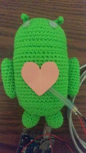
I used Arduino with force sensor. I edited the sample melody (twinkle twinkle little star) sketch code to make the piezo buzzer play the meolody and use the force sensor to control the melody’s tempo. With different value detected by the force sensor, the tempo of the melody will change. Also, to make the input and output coincide I attache both the piezo buzzer and force sensor to the android toy. Lastly, I uploaded the code and took pictures of the result.
Components
- 1 Arduino
- 1 Piezo
- 1 Breadboard
- 1 force sensor
- 1 Andoird toy
Code
/*
Connections For this application;
Use Freeduino-RichBoard made by www.EmbeddedMarket.com

1. Connect Digital Pin 9 to Buz pin in Section 9 on Freeduino Board

2. Connect USB Cable

*/


/* Melody
 * (cleft) 2005 D. Cuartielles for K3
 *
 * This example uses a piezo speaker to play melodies. It sends
 * a square wave of the appropriate frequency to the piezo, generating
 * the corresponding tone.
 *
 * The calculation of the tones is made following the mathematical
 * operation:
 *
 * timeHigh = period / 2 = 1 / (2 * toneFrequency)
 *
 * where the different tones are described as in the table:
 *
 * note frequency period timeHigh
 * c 261 Hz 3830 1915
 * d 294 Hz 3400 1700
 * e 329 Hz 3038 1519
 * f 349 Hz 2864 1432
 * g 392 Hz 2550 1275
 * a 440 Hz 2272 1136
 * b 493 Hz 2028 1014
 * C 523 Hz 1912 956
 *
 * http://www.arduino.cc/en/Tutorial/Melody
 */

int speakerPin = 7;
// Do we want debugging on serial out? 1 for yes, 0 for no
//int DEBUG = 1;
int potPin = 2;
int val = 0;

int length = 15; // the number of notes

//twinkle twinkle little star
char notes[] = "ccggaag ffeeddc ggffeed ggffeed ccggaag ffeeddc "; // a space represents a rest
int beats[] = { 1, 1, 1, 1, 1, 1, 2, 1, 1, 1, 1, 1, 1, 2, 4 };
int tempo = 200;

void playTone(int tone, int duration) {
 for (long i = 0; i < duration * 1000L; i += tone * 2) {
 digitalWrite(speakerPin, HIGH);
 delayMicroseconds(tone);
 digitalWrite(speakerPin, LOW);
 delayMicroseconds(tone);
 }
}

void playNote(char note, int duration) {
 char names[] = { 'c', 'd', 'e', 'f', 'g', 'a', 'b', 'C' };
 int tones[] = { 1915, 1700, 1519, 1432, 1275, 1136, 1014, 956 };

 // play the tone corresponding to the note name
 for (int i = 0; i < 8; i++) {
 if (names[i] == note) {
 playTone(tones[i], duration);
 }
 }
}

void setup() {
 pinMode(speakerPin, OUTPUT);
 Serial.begin(9600); // Set serial out if we want debugging
 Serial.println("ready");
}

void loop() {
 val = analogRead(potPin); //read value from the sensor
 if (tempo>500){
 tempo = 100;
 } else{
 tempo = tempo+val;
 }

for (int i = 0; i < length; i++) {
 if (notes[i] == ' ') {
 delay(beats[i] * tempo); // rest
 } else {
 playNote(notes[i], beats[i] * tempo);
 }

 // pause between notes
 delay(tempo / 2);
 }
}

//read a string from the serial and store it in an array
//you must supply the array variable
void readSerialString (char *strArray) {
 int i = 0;
 if(!Serial.available()) {
 return;
 }
 while (Serial.available()) {
 strArray[i] = Serial.read();
 i++;
 }
}

Prototyping Mindfully
In the article “Prototyping: Generating ideas or Cargo Cult Designs,” the author discussed the dilemma and limitation of prototyping. In the authors view, prototyping has been a successful and useful tool for interaction designers to foster creativity and to facilitate their design process and discussion with other team members. However, one should be careful in term of over promising the feasibility of these prototypes. In order to prevent having a feature that is not actually feasible in reality, the author recommend the designers to conduct researches about the technologies and their limitations.
In his article, the author argues that while prototyping provides a common focal and discussion point among different team members, over emphasis on the hypothetical features on the prototype could cause illusion to the team members regarding the reality of making these features into an actual product. This false belief of the pseudo feature of a prototype is what the author refers to as a “Cargo Cult Design.” Furthermore, in order to fix this problem, the author proposed that interaction designers should conduct prior researches regarding the background of the potential technologies and their limitations before designing the hypothetical features of a prototype. In this way, while having the discussion with the team, the designers will also have an idea about what’s actually feasible in reality rather than falling into the illusions that everything is feasible. In addition, the author also suggest that in order to prevent a prototype falls into a cargo cult experience, designers should realize that prototyping a helping the team to explore rather than an end product.
Lab 04
Description
I used Arduino with force sensor. I edited the sample process sketch code to turn on the circle into squares with changing color and changing the corners with round angles via force sensor interaction. With different value detected by the force sensor, the color and the size of the square will change as well as the degree of angles of its corners. Lastly, I uploaded the code and took pictures of the result.
Components
- 1 Arduino
- 3 LED
- 3 Resistor (220Ω)
- 1 Breadboard
- One force sensor
Code
/* PROCESSING SKETCH
 * Arduino Ball Paint
 * (Arduino Ball, modified 2008)
 * ----------------------
 *
 * Draw a ball on the screen whose size is
 * determined by serial input from Arduino.
 *
 * Created 21 September 2016
 * Noura Howell
 * Edited by Owen Hsiao on Sep. 23 2016
 */


import processing.serial.*;
// Change this to the portname your Arduino board
String portname = "COM3"; // or "COM5"
Serial port;
String buf="";
int cr = 13; // ASCII return == 13
int lf = 10; // ASCII linefeed == 10

int serialVal = 0;

int n = serialVal + int(random(10));


void setup() {
 size(300,300);
 frameRate(10);
 smooth();
 background(40,40,40);
 noStroke();
 port = new Serial(this, portname, 9600);
}

void draw() {
 // erase the screen
 background(40, 40, 40);

// draw the ball
 fill(255, serialVal, 255/n);
 //ellipse(150,150,serialVal,serialVal);
 rect(70, 70, serialVal+30, serialVal +30, serialVal/20);
}

// called whenever serial data arrives
void serialEvent(Serial p) {
 int c = port.read();
 if (c != lf && c != cr) {
 buf += char(c);
 }
 if (c == lf) {
 serialVal = int(buf);
 println("val="+serialVal);
 buf = "";
 }
}
Encalming Technology
In their article, Weiser and Brown give the Ambient Information Systems a name called Calm Technology. According to Weiser and Brown, “enhanced peripheral reach increases our knowledge and so our ability to act without increasing information overload” (P.2, Weiser and Brown 1995). This type of technology provide the users information they need to know for their actions in the background and only brings the user’s attention to these information when needed. The best example, which illuminate their point, in my view, is the inner office windows. According to Weiser and Brown, adding inner office windows in a office “connects people inside to the nearby world” by providing information such as “motion of other people down the hall (it is time for lunch; the big meeting is starting) or noticing the same person peeking in for the third time while you are on the phone (they really want to see me; I forgot an appointment)” ,etc.
These kind of technology is very exciting because it utilize the senses that are normally peripheral to us to provide information which enhances the users’ actions. For example, in the “Dangling String” example, The users will be able to notice something wrong with the bit transmission by some irregular sounds from the strings. In this way the users can focus on other actions and shift their attention to the data transmission part of the system only when the irregular sounds occur. As Weiser and Brown mentioned, in this way, “more information could be more encalming.” (P5, Weiser & Brown, 1995).
Lab03
Description
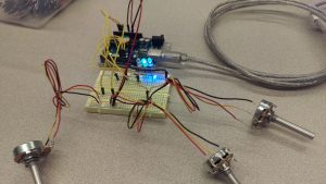
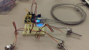
I used Arduino with three LEDs (red, blue and green) and 3 potentiometers. I edited the sketch code to control the red LED’s blinking speed and the brightness of green and blue LED with three different potentiometers . The result, as shown in the image below, is quite as expected. The blinking speed of the red LED and the brightness of the green and blue LED is controlled by the plot sucessfully.
Components
- 1 Arduino
- 3 LED
- 3 Resistor (220Ω)
- 1 Breadboard
- 3 Pots
Code
/*
 Analog Input
 Demonstrates analog input by reading an analog sensor on analog pin 0 and
 turning on and off a light emitting diode(LED) connected to digital pin 13.
 The amount of time the LED will be on and off depends on
 the value obtained by analogRead().

The circuit:
 * Potentiometer attached to analog input 0
 * center pin of the potentiometer to the analog pin
 * one side pin (either one) to ground
 * the other side pin to +5V
 * LED anode (long leg) attached to digital output 13
 * LED cathode (short leg) attached to ground

* Note: because most Arduinos have a built-in LED attached
 to pin 13 on the board, the LED is optional.

Created by David Cuartielles
 modified 20 Sep. 2016
 By Owen Hsiao

This example code is in the public domain.

http://www.arduino.cc/en/Tutorial/AnalogInput

*/

int sensorPin = A0; // select the input pin for the potentiometer
 //int bsensorPin = A1; // select the input pin for the potentiometer
 //int ledPin = 13; // select the pin for the LED
 int ledPin = 9;
 //int bledPin = 10;
 //int greenledPin = 11;
 int sensorValue = 0; // variable to store the value coming from the sensor
 //int bsensorValue = 0; // variable to store the value coming from the sensor

int potPin = A1; // Analog input pin that the potentiometer is attached to
 int potValue = 0; // value read from the pot

int potPin2 = A2; // Analog input pin that the potentiometer is attached to
 int pot2Value = 0; // value read from the pot
 int led = 10; // PWM pin that the LED is on. n.b. PWM 0 is on digital pin 10
 int led2 = 11; // PWM pin that the LED is on. n.b. PWM 0 is on digital pin 11

void setup() {
 // declare the ledPin as an OUTPUT:
 pinMode(ledPin, OUTPUT);
 // declare the bledPin as an OUTPUT:
 // pinMode(bledPin, OUTPUT);

// initialize serial communications at 9600 bps:
 Serial.begin(9600);
 // declare the led pin as an output:
 pinMode(led, OUTPUT);

// initialize serial communications at 9600 bps:
 Serial.begin(9600);
 // declare the led pin as an output:
 pinMode(led2, OUTPUT);
 }

void loop() {
 // read the value from the sensor:
 sensorValue = analogRead(sensorPin);
 // turn the ledPin on
 digitalWrite(ledPin, HIGH);
 // stop the program for <sensorValue> milliseconds:
 delay(sensorValue);
 // turn the ledPin off:
 digitalWrite(ledPin, LOW);
 // stop the program for for <sensorValue> milliseconds:
 delay(sensorValue);

potValue = analogRead(potPin); // read the pot value
 analogWrite(led, potValue/4); // PWM the LED with the pot value (divided by 4 to fit in a byte)
 Serial.println("hello"); // print the pot value back to the debugger pane
 delay(10); // wait 10 milliseconds before the next loop

pot2Value = analogRead(potPin2); // read the pot value
 analogWrite(led2, pot2Value/5); // PWM the LED with the pot value (divided by 4 to fit in a byte)
 Serial.println("hello"); // print the pot value back to the debugger pane
 delay(10); // wait 10 milliseconds before the next loop
 }


Lab 02
Description
I used Arduino with three LEDs (red, blue and green). I edited the sketch code to turn on the LED with keyboard interaction. Each enter of the corresponding key is 255/10 of the brightness. I also use bubble rap to create an air balloon as a diffuser. I then turn the red and blue LED to 127 and green LED to zero to make a purple air balloon. However, the result is not as expected. Blue and Red are still somehow separated. Lastly, I uploaded the code and took pictures of the result.
Components
- 1 Arduino
- 3 LED
- 3 Resistor (220Ω)
- 1 Breadboard
- One difuser
Code
/*
 * Serial RGB LED
 * ---------------
 * Serial commands control the brightness of R,G,B LEDs
 *
 * Command structure is "<colorCode><colorVal>", where "colorCode" is
 * one of "r","g",or "b" and "colorVal" is a number 0 to 255.
 * E.g. "r0" turns the red LED off.
 * "g127" turns the green LED to half brightness
 * "b64" turns the blue LED to 1/4 brightness
 *
 * Created 18 October 2006
 * copyleft 2006 Tod E. Kurt <tod@todbot.com
 * http://todbot.com/
 */

char serInString[100]; // array that will hold the different bytes of the string. 100=100characters;
 // -> you must state how long the array will be else it won't work properly
char colorCode;
int colorVal;

int redPin = 9; // Red LED, connected to digital pin 9
int greenPin = 10; // Green LED, connected to digital pin 10
int bluePin = 11; // Blue LED, connected to digital pin 11

void setup() {
 pinMode(redPin, OUTPUT); // sets the pins as output
 pinMode(greenPin, OUTPUT);
 pinMode(bluePin, OUTPUT);
 Serial.begin(9600);
 analogWrite(redPin, 127); // set them all to mid brightness
 analogWrite(greenPin, 127); // set them all to mid brightness
 analogWrite(bluePin, 127); // set them all to mid brightness
 Serial.println("Please enter color corresponding key to change the brightness (i.e. 'r' for RED; ''g' for GREEN; and 'b' for BLUE :");
}

void loop () {
 // clear the string
 memset(serInString, 0, 100);
 //read the serial port and create a string out of what you read
 readSerialString(serInString);

 colorCode = serInString[0];
 if( colorCode == 'r' || colorCode == 'g' || colorCode == 'b' ) {
 colorVal = atoi(serInString+1);
 colorVal = strlen(serInString);
 colorVal = (colorVal*255/10); // increase the value by 10% by calculating the number of times you type r, g or b defines the brightness (% of)
 if (colorVal>255)
 { // need a way to turn off colors
 colorVal = 0;}
 Serial.print("setting color ");
 Serial.print(colorCode);
 Serial.print(" to ");
 Serial.print(colorVal);
 Serial.println();
 serInString[0] = 0; // indicates we've used this string
 if(colorCode == 'r')
 analogWrite(redPin, colorVal);
 else if(colorCode == 'g')
 analogWrite(greenPin, colorVal);
 else if(colorCode == 'b')
 analogWrite(bluePin, colorVal);
 }

 delay(100); // wait a bit, for serial data
}

//read a string from the serial and store it in an array
//you must supply the array variable
void readSerialString (char *strArray) {
 int i = 0;
 if(!Serial.available()) {
 return;
 }
 while (Serial.available()) {
 strArray[i] = Serial.read();
 i++;
 }
}

Lab 01
Description
I used Arduino with a red LED. I edited the sketch code to turn on the LED for 10 seconds and then off for 2 seconds. Uploaded the code and took pictures of the result.
Components
- 1 Arduino
- 1 LED
- 1 Resistor (220Ω)
- 1 Breadboard
Code
/*
 Blink
 Turns on an LED on for one second, then off for one second, repeatedly.

Most Arduinos have an on-board LED you can control. On the Uno and
 Leonardo, it is attached to digital pin 13. If you're unsure what
 pin the on-board LED is connected to on your Arduino model, check
 the documentation at http://www.arduino.cc

This example code is in the public domain.

modified 8 May 2014
 by Scott Fitzgerald
 */


// the setup function runs once when you press reset or power the board
void setup() {
 // initialize digital pin 13 as an output.
 pinMode(13, OUTPUT);
}

// the loop function runs over and over again forever
void loop() {
 digitalWrite(13, HIGH); // turn the LED on (HIGH is the voltage level)
 delay(10000); // wait for a second
 digitalWrite(13, LOW); // turn the LED off by making the voltage LOW
 delay(2000); // wait for a second
}
