Lab 04

Description

I used Arduino with force sensor. I edited the sample process sketch code to turn on the circle into squares with changing color and changing the corners with round angles via force sensor interaction. With different value detected by the force sensor, the color and the size of the square will change as well as the degree of angles of its corners. Lastly, I  uploaded the code and took pictures of the result.

Components

  • 1 Arduino
  • 3 LED
  • 3 Resistor (220Ω)
  • 1 Breadboard
  • One force sensor

Code

/* PROCESSING SKETCH
 * Arduino Ball Paint
 * (Arduino Ball, modified 2008)
 * ---------------------- 
 *
 * Draw a ball on the screen whose size is
 * determined by serial input from Arduino.
 *
 * Created 21 September 2016
 * Noura Howell
 * Edited by Owen Hsiao on Sep. 23 2016
 */


import processing.serial.*;
// Change this to the portname your Arduino board
String portname = "COM3"; // or "COM5"
Serial port;
String buf="";
int cr = 13; // ASCII return == 13
int lf = 10; // ASCII linefeed == 10

int serialVal = 0;

int n = serialVal + int(random(10));


void setup() {
 size(300,300);
 frameRate(10);
 smooth();
 background(40,40,40);
 noStroke();
 port = new Serial(this, portname, 9600); 
}

void draw() {
 // erase the screen
 background(40, 40, 40);

// draw the ball
 fill(255, serialVal, 255/n);
 //ellipse(150,150,serialVal,serialVal);
 rect(70, 70, serialVal+30, serialVal +30, serialVal/20);
}

// called whenever serial data arrives
void serialEvent(Serial p) {
 int c = port.read();
 if (c != lf && c != cr) {
 buf += char(c);
 }
 if (c == lf) {
 serialVal = int(buf);
 println("val="+serialVal); 
 buf = ""; 
 }
}


Lab 4 FSR, Bouncy Balls, Music, and Color

Description

Video

I made a bouncy balls animation where the FSR can control the gravity of the bouncy balls. I’ve attached a youtube video. Music is accompanied with the bouncy ball experienced. Also I added features that will let users control the color of the balls through mouse and control the color of backgrounds through keyboards. The user can also control the spring of the balls through up and down keys.

I didn’t focus as much on the mechanical part of the lab because I spent too much time playing with the animation and digging into the tutorial. Right now, I’m just controlling the force through my hands. But I definitely had a lot of fun playing with this lab and am looking forward to apply some mechanical concepts in the future.

Processing Code

import processing.serial.*;
import processing.sound.*;
SoundFile file;

// Change this to the portname your Arduino board
String portname = "/dev/cu.usbmodem1421"; // or "COM5"
Serial port;
String buf="";
int cr = 13; // ASCII return == 13
int lf = 10; // ASCII linefeed == 10
int SerialVal = 0;
float r = 0;
float g = 0;
float b = 0;

int numBalls = 40;
float spring = 0.05;
float gravity = 0.03;
float friction = -0.9;
Ball[] balls = new Ball[numBalls];

int barWidth = 5;
int lastBar = -1;

void setup() {
size(800, 800);
for (int i = 0; i < numBalls; i++) { balls[i] = new Ball(random(width), random(height), random(30, 70), i, balls); } noStroke(); file = new SoundFile(this, "spaceBeat.wav"); file.play(); port = new Serial(this, portname, 9600); } void draw() { background(r, g ,b); for (Ball ball : balls) { ball.collide(); ball.move(); ball.display(); } if (keyPressed == true && keyCode == UP) { spring += 0.01; } else if (keyPressed == true && keyCode == DOWN) { spring -= 0.01; } else if (keyPressed == true && key == 'r') { r += 10; } else if (keyPressed == true && key == 'R') { r -= 10; } else if (keyPressed == true && key == 'g') { g += 10; } else if (keyPressed == true && key == 'G') { g -= 10; } else if (keyPressed == true && key == 'b') { b += 10; } else if (keyPressed == true && key == 'B') { b -= 10; } else if (keyPressed == true && key == 'S' || key == 's') { friction = -0.9; spring = 0.05; r=0; g=0; b=0; } int whichBar = mouseX / barWidth; if (whichBar != lastBar) { int barX = whichBar * barWidth; fill(barX, mouseY, 66); rect(barX, 0, barWidth, height); lastBar = whichBar; } } class Ball { float x, y; float diameter; float vx = 0; float vy = 0; int id; Ball[] others; Ball(float xin, float yin, float din, int idin, Ball[] oin) { x = xin; y = yin; diameter = din; id = idin; others = oin; } void collide() { for (int i = id + 1; i < numBalls; i++) { float dx = others[i].x - x; float dy = others[i].y - y; float distance = sqrt(dx*dx + dy*dy); float minDist = others[i].diameter/2 + diameter/2; if (distance < minDist) { float angle = atan2(dy, dx); float targetX = x + cos(angle) * minDist; float targetY = y + sin(angle) * minDist; float ax = (targetX - others[i].x) * spring; float ay = (targetY - others[i].y) * spring; vx -= ax; vy -= ay; others[i].vx += ax; others[i].vy += ay; } } } void move() { vy += gravity; x += vx; y += vy; if (x + diameter/2 > width) {
x = width - diameter/2;
vx *= friction;
}
else if (x - diameter/2 < 0) { x = diameter/2; vx *= friction; } if (y + diameter/2 > height) {
y = height - diameter/2;
vy *= friction;
}
else if (y - diameter/2 < 0) { y = diameter/2; vy *= friction; } } void display() { ellipse(x, y, diameter, diameter); } } // called whenever serial data arrives void serialEvent(Serial p) { int c = port.read(); if (c != lf && c != cr) { buf += char(c); } if (c == lf) { SerialVal = int(buf); println("val="+SerialVal); gravity = SerialVal/1000; println("gravity="+gravity); buf = ""; } }

Arduino Code

/* Photocell simple testing sketch.

Connect one end of the photocell to 5V, the other end to Analog 0.
Then connect one end of a 10K resistor from Analog 0 to ground
Connect LED from pin 11 through a resistor to ground
For more information see http://learn.adafruit.com/photocells */

int photocellPin = 0; // the cell and 10K pulldown are connected to a0
int photocellReading; // the analog reading from the sensor divider
int LEDpin = 11; // connect Red LED to pin 11 (PWM pin)
int LEDbrightness; //
void setup(void) {
// We'll send debugging information via the Serial monitor
Serial.begin(9600);
}

void loop(void) {
photocellReading = analogRead(photocellPin);

// LED gets brighter the darker it is at the sensor
// that means we have to -invert- the reading from 0-1023 back to 1023-0
photocellReading = 1023 - photocellReading;
//now we have to map 0-1023 to 0-255 since thats the range analogWrite uses
LEDbrightness = map(photocellReading, 0, 1023, 255, 0);
analogWrite(LEDpin, LEDbrightness);

Serial.println(photocellReading);

delay(100);
}

[Lab04] Roses are red, I am blue because midterm season.

Description

In this lab, I fit the force sensitive resistor between two airpacks. Upon compression, a rose is generated in Processing. This rose is created from arcs against a gradient background.

Materials

  • Arduino, LED, jumper, cables
  • Processing
  • Force sensitive resistor
  • Air packs


import processing.serial.*;

String portname = "/dev/cu.usbmodem1421";
Serial port;
String buf="";
int cr = 13;
int lf = 10;
int serialVal = 0;
int shift = 0;

void setup() {
size(800,800,P3D);
port = new Serial(this, portname, 9600);

noStroke();
colorMode(RGB, 400);
for (int i = 200; i < 400; i++) { for (int j = 200; j<400; j++) { stroke(i,j,0); point(i,j); }}} //} // void draw() { noStroke(); colorMode(RGB, 400); for (int i = 0; i < 800; i++) { for (int j = 0; j<800; j++) { stroke(i,j,0); point(i,j); } } stroke(255,0,255); noFill(); //ellipse(150,150,serialVal, serialVal); genRose((int) (serialVal*0.7),0, 350, 350); genRose((int) (serialVal*0.5), (int) HALF_PI, 350, 350);; if (serialVal > 400) {
genRose((int) (serialVal*0.5) ,0, 600, 600);
genRose((int) (serialVal*0.3), (int) HALF_PI, 600, 600);;
if (serialVal>500) {
genRose((int) (serialVal*0.5) ,0, 200, 200);
genRose((int) (serialVal*0.3), (int) HALF_PI, 200, 200);;

genRose((int) (serialVal*0.3) ,0, 700, 700);
genRose((int) (serialVal*0.1), (int) HALF_PI, 700, 700);;
if (serialVal > 600) {
genRose((int) (serialVal*0.3) ,0, 200, 600);
genRose((int) (serialVal*0.1), (int) HALF_PI, 200, 600);;
genRose((int) (serialVal*0.3) ,0, 600, 200);
if (serialVal > 700) {
genRose((int) (serialVal*0.1), (int) HALF_PI, 600, 200);;
genRose((int) (serialVal*0.3) ,0, 500, 500);
genRose((int) (serialVal*0.1), (int) HALF_PI, 500, 500);;
}
}
}
}

}

void genRose(int serialVal, int shift, int x, int y) {
fill(255,0,0);
arc(x,y,serialVal*0.9, serialVal, 0+shift, HALF_PI+shift);
arc(x,y,serialVal*1.1, serialVal*1.1, HALF_PI+shift, PI+shift);

fill(200,0,0);
arc(x,y,serialVal*0.9, serialVal, PI+shift, PI+HALF_PI+shift);
arc(x,y,serialVal*1.1, serialVal*1.1, PI+HALF_PI+shift, PI+PI+shift);
fill(175,0,0);
arc(x,y,serialVal/2, (serialVal/2)*0.8, 0+shift,PI+shift);
arc(x,y,serialVal/2, (serialVal/2) *0.8, (HALF_PI * 3)+shift,(PI * 2) +shift);
fill(150,0,0);
arc(x,y,(serialVal/4)*0.9, serialVal/4, 0+shift,HALF_PI+shift);
arc(x,y,(serialVal/4) *0.9, serialVal/4, PI+shift,PI+HALF_PI+shift);
fill(175,0,0);
arc(350,350,serialVal/8, (serialVal/8) *0.9, PI+HALF_PI+shift,PI+PI+shift);
arc(350,350,serialVal/8, (serialVal/8) *0.9, HALF_PI+shift,PI+shift);

}

void serialEvent(Serial p) {
int c = port.read();
if (c != lf && c != cr) {
buf += char(c);
} if (c==lf) {
serialVal = int(buf);
println("val="+serialVal);
buf= "";
}
}

Picture of the airpacks.
img_0420

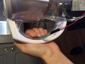
Now I have created a garden of roses. Using a photocell would have made more sense because sunshine correlates to flowers. But also, if I attach this FSR to a water container like my water filter (will not be bringing this to class tomorrow), I can map it to the idea of watering plants.

image1-1