Trapdoor Cuckoo Clock

Description:

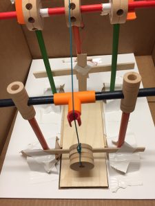
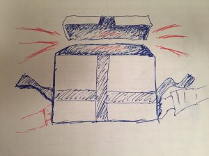
Our group wanted to attempt an unconventional cuckoo clock, counter to the example we saw in class with the 4-bar joint. Instead of a cuckoo that emerged horizontally from the door, we designed a cuckoo that plunged through a trapdoor instead. The primary mechanism used to move the trapdoor and lower the cuckoo through the opening is a pulley system. As the pulley is pulled in one direction, the trapdoor moves out of the way to reveal an exit. As the pulley is pulled and the trapdoor is moved back, the cuckoo also lowers. The cuckoo is mitigated from falling outside the bounds of the trapdoor exit until the opening is wide enough for it to plunge through. The cuckoo can then continue to be lowered, or reigned back into the clock by pulling the pulley in the opposite direction. The trapdoor is prevented from collapsing on the cuckoo prematurely by means of (1) the distances used in both the strings affixed to the door and the cuckoo, and (2) the rotational distance between the door and the peg that pushes it back into place.

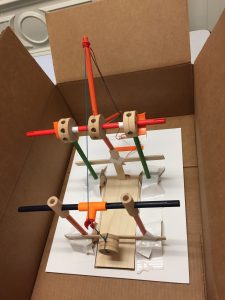
To hold the system in place and direct accurate movement, we have in place four poles around the trapdoor’s perimeter (but not affixed to the trapdoor). These poles are taped securely to the surface of the foam board/clock base. While there are three gears in our structure, only the center one is unrestrained by a foundational support component. For our design, it is imperative that thread lines are measured to have sufficient tension and slack when appropriate. Otherwise, the system will fail. If the support structure also shifts (whether at foundation or at suspension), the system is likely to fail due to the shifting of the trapdoor in and out of place. Also necessary is a wall to prevent the cuckoo from traveling with the trapdoor as it slides back, as opposed to falling through the exit.

We think this cuckoo clock mechanism design is appropriate, considering the majority of cuckoo clocks hang on the wall, and so have room beneath them that can be utilized.

Components Used:

  • 7 gears (4 for foundational support, 2 for suspended support, 1 for pulley system)
  • 1 long stick
  • 2 mid-length sticks
  • 5 short sticks (sizes must be relative; 3 for pulley system)
  • 1 cuckoo (made out of a spool, suspended by string)
  • two cuts of string (1 for the trapdoor, 1 for the cuckoo)
  • 1 relatively large piece of balsa wood for the trapdoor
  • 3 relatively narrow pieces of balsa wood for support/error-prevention
  • 1 T-pipe
  • 2 straight joints with medial socket
  • 1 claw
  • 1 foam board sheet
  • duct tape
  • X-acto knife and cutting board
  • sufficient string for the pulley system


img_6360 img_6359

RR06: VR

As you have experienced the HTC Vive, 1) What was the part of the experience you liked most? How might you enhance or expand the experience? 2) What was the part of your experience you liked least and how might the design team address/improve it?

I observed people this previous week while they interacted with the HTC Vive within virtual reality; however, I have used the HTC Vive before to explore terrains, as well as illustrate in TiltBrush. The experience I liked most was being able to explore environments (essentially, new worlds) within virtual reality, and truly feel like I am there. I’m a gamer with an active imagination, and so I couldn’t help myself from thinking about the worlds I could see, what environments that are currently inaccessible to me would then be accessible. I might try to expand on this aspect of exploration by exploring modes of transportation, and making that experience feel as real as other features are.

The part of my experience I liked the least was actually creating in TiltBrush. I think the concept is fun and allows barriers to be broken down with regard to accessibility to drawing/creativity. Where it breaks for me is the difficulty with depth perception. I don’t know how deep my brush is in this limitless canvas, and that directly affects how my creation will unfold. As a design intervention, aside from visual cues within the virtual environment, I would think a tensile sensor would be helpful on your arm. The further your reach, the more tension/resistance is applied to your arm. I can see how this would be limiting to free form drawing, which is unfortunate. But the lack of depth perception cues when you haven’t assigned a focal point in 3D space (such as a rock, or a model to draw AROUND) is quite frustrating.


Lab07: Crimson Crawler

Description:

I had so much fun assembling this crawler, thinking about the mechanics of a one-legged crawler, and how weight would need to be distributed to get it to move in a linear direction. While hardwood floor doesn’t allow for enough friction between it and the tips of the paperclips, the knit of my scarf produced similar (but slightly better) results. I discovered that my crawler crawls best on a surface with some teeth to it, such as the cover of one of my sketchbooks. Through experimentation I discovered that in order to get it to walk straighter, I needed to reprogram the arduino such that it didn’t have the servomotor have one single sweeping pattern.

Components Used:

  • 1 Arduino
  • 1 Servomotor
  • 1 Breadboard
  • 1 pot (but unused in the sketch below)
  • 1 large paperclip, 1 medium paperclip
  • 1 Futaba servomotor box
  • 1 X-factor nail polish bottle
  • electrical tape

Code:

/*
 * Servo Control Serial
 * modified for TUI October 2007
 * Servo Serial Better
 * -------------------
 *
 * Created 18 October 2006
 * copyleft 2006 Tod E. Kurt <tod@todbot.com>
 * http://todbot.com/
 *
 * adapted from "http://itp.nyu.edu/physcomp/Labs/Servo"
 */
#include <Servo.h>

Servo myservo; // create servo object to control a servo
int servoPin = 7; // Control pin for servo motor

int pos = 0; // variable used to store data from serial port

int minPulse = 0; // minimum pulse width
int maxPulse = 100; // maximum pulse width

void setup() {
 pinMode(servoPin, OUTPUT); // Set servo pin as an output pin
 pos = minPulse; // Set the motor position to the minimum
 Serial.begin(9600); // connect to the serial port
 Serial.println("Servo control program ready");
 myservo.attach(7); // attaches the servo on pin 9 to the servo object
}

void loop() {
 for (pos = minPulse; pos <= maxPulse; pos += 1) { // goes from 0 degrees to 180 degrees
 // in steps of 1 degree
 myservo.write(pos); // tell servo to go to position in variable 'pos'
 delay(7); // waits 7ms for the servo to reach the position
 }
 for (pos = maxPulse; pos >= minPulse; pos -= 1) { // goes from 180 degrees to 0 degrees
 myservo.write(pos); // tell servo to go to position in variable 'pos'
 delay(5); // waits 5ms for the servo to reach the position
 }
}


AND ALSO

/*
 * Servo Control Serial
 * modified for TUI October 2007
 * Servo Serial Better
 * -------------------
 *
 * Created 18 October 2006
 * copyleft 2006 Tod E. Kurt <tod@todbot.com>
 * http://todbot.com/
 *
 * adapted from "http://itp.nyu.edu/physcomp/Labs/Servo"
 */
#include <Servo.h>

Servo myservo; // create servo object to control a servo
int servoPin = 7; // Control pin for servo motor

int pos = 0; // variable used to store data from serial port

int minPulse = 0; // minimum pulse width
int maxPulse = 115; // maximum pulse width
int correction = 55;
int count = 0;

void setup() {
 pinMode(servoPin, OUTPUT); // Set servo pin as an output pin
 pos = minPulse; // Set the motor position to the minimum
 Serial.begin(9600); // connect to the serial port
 Serial.println("Servo control program ready");
 myservo.attach(7); // attaches the servo on pin 9 to the servo object
}

void loop() {
 for (count = 0; count <= 2; count +=1) {
 for (pos = correction; pos <= maxPulse; pos += 1) { // goes from 0 degrees to 180 degrees
 // in steps of 1 degree
 myservo.write(pos); // tell servo to go to position in variable 'pos'
 delay(7); // waits 7ms for the servo to reach the position
 }
 for (pos = maxPulse; pos >= correction; pos -= 1) { // goes from 180 degrees to 0 degrees
 myservo.write(pos); // tell servo to go to position in variable 'pos'
 delay(5); // waits 5ms for the servo to reach the position
 }
}
 for (count = 0; count <= 7; count +=1) {
 for (pos = minPulse; pos <= correction; pos += 1) { // goes from 0 degrees to 180 degrees
 // in steps of 1 degree
 myservo.write(pos); // tell servo to go to position in variable 'pos'
 delay(7); // waits 7ms for the servo to reach the position
 }
 for (pos = correction; pos >= minPulse; pos -= 1) { // goes from 180 degrees to 0 degrees
 myservo.write(pos); // tell servo to go to position in variable 'pos'
 delay(5); // waits 5ms for the servo to reach the position
 }
}


}


img_6347-mov img_6346-mov

Lab06: Hands of a Clock

Description:

Unfortunately, the wires I soldered to my DC motor snapped off and additionally got stuck in the breadboard; but, I’ve seriously considered certain applications that I was in the middle of developing. When the FSR has pressure applied to it, the DC motor spins more swiftly. So, as pressure is applied to the FSR, it is as though we are rushing forward through time (similar to Hermione’s time-turner pendant). Additionally, I considered this process to be similar to how an electric pencil sharpener works. When pressure is applied to the pencil sharpener, it knows to spin and sharpen your pencil.

Components Used:

  • 1 Arduino
  • 1 Resistor (1kΩ)
  • 1 Breadboard
  • 1 FSR potentiometer
  • 1 DC motor
  • 1 transistor
  • 1 diode

Code:

/*
 * one pot fades one motor
 * modified version of AnalogInput
 * by DojoDave <http://www.0j0.org>
 * http://www.arduino.cc/en/Tutorial/AnalogInput 
 * Modified again by dave
 */

int potPin = A0; // select the input pin for the potentiometer
int motorPin = 9; // select the pin for the Motor
int val = 0; // variable to store the value coming from the sensor
void setup() {
 Serial.begin(9600);
}
void loop() {
 val = 1024 - analogRead(potPin); // read the value from the sensor, between 0 - 1024, and then subtract from 1024
 Serial.println(val);
 analogWrite(motorPin, val/11); // analogWrite can be between 0-255
}


img_6316

Thoughtless Act: There’s a Phone in Your Boot

My thoughtless act is actually my own. Women’s fashion is usually plagued by having a deficiency in number of pockets, or in size of pockets. And as mobile phones have been getting larger and larger, it becomes frustratingly difficult to carry a phone around without completely occupying a hand. A staple to my wardrobe are knee-high boots, though.

One day a couple years ago, a gentleman made a comment about how he noticed I had a phone in my boot. I wasn’t sure when that behavior started, or what event it was spurred by, but his comment caught me by surprise. I supposed it was a peculiar thing to do, but it felt easy and comfortable and so made its way into my life as a natural habit. I still continue this behavior, and occasionally will receive similar comments that serve no purpose other than to point out, and verify, that there is a phone in my boot. Only once in the airport did a man claim with joy, “Oh, my wife does that, too!”

While I think that the boot itself solves the problem of phone storage/ferrying without physical design manipulation, it could probably be improved upon. For instance, sometimes the shaft of my boot has so much free room inside that my phone slips all the way down to my ankle, making retrieval actually quite difficult. This was not a problem I encountered until recently, needing to replace an older pair of boots with a newer one with more supple leather and a wider shaft. I think installing a small stopper somewhere within the boot, one that was unobtrusive and comfortable for my calf, would greatly alleviate my strain in reaching for my phone when it’s fallen too far.

RR05: Hobonichi Techo Daily Planner

I tried to transition to planning my days in a digital calendar; however, I found my experience lackluster, and soon found myself not tracking my days at all. The lack of a customizable experience — to the extent that I felt like it was easily identified as my planner and not anyone else’s — pulled me back to paper planners. But, my former Moleskine planners were ill designed for sufficient, flexible realestate on a page. I looked into creating my own bullet journal, but lack the time to make one completely to my liking.

So, I did some research and found myself purchasing a Hobonichi Techo Daily Planner. It’s a daily planner that is made in Japan that is rather compact, with Tomoe River paper (which before I ordered the planner meant absolutely nothing to me, because I had never experienced writing on it before), and bound in a way such that it lays flat. I was very nervous with this purchase, having gone from store to local store hunting for a copy for me to touch, maybe run a pen over. I am very particular about how my notebooks feel as I use them, and how much of a struggle it is to write close to the binding. My previous planners did not hold ink very well, or forced a structure that did not suit my lifestyle. These things you unfortunately do not realize until after attempting to use the planner for a while.

Immediately, when the journal arrived, I ran my fingers over the cover, the Tomoe river paper, and tested the paper with a fountain pen. To my pleasant surprise, the ink did not feather nor bleed through onto the next page. I was thrilled to find a resilient and compact planner with just enough printed structure that would suit my commuter life, and I have to say I am sold for life.

House from Up

Description:

I decided to channel energy from the Disney movie Up. I programmed the piezo to output the theme song from the movie when someone steps on the doorstep of the house. Let’s pretend the house is up in the sky, per the cotton of cloud beneath it. :}

Components Used:

  • 1 Arduino
  • 1 Resistor (10kΩ)
  • 1 Breadboard
  • 1 piezo
  • 1 FSR potentiometer
  • 1 3D printed house (out of PLA)
  • cotton (to simulate a cloud)

Code:

/* Play Melody
 * -----------
 *
 * Program to play melodies stored in an array, it requires to know
 * about timing issues and about how to play tones.
 *
 * The calculation of the tones is made following the mathematical
 * operation:
 *
 * timeHigh = 1/(2 * toneFrequency) = period / 2
 *
 * where the different tones are described as in the table:
 *
 * note frequency period PW (timeHigh) 
 * c 261 Hz 3830 1915 
 * d 294 Hz 3400 1700 
 * e 329 Hz 3038 1519 
 * f 349 Hz 2864 1432 
 * g 392 Hz 2550 1275 
 * a 440 Hz 2272 1136 
 * b 493 Hz 2028 1014 
 * C 523 Hz 1912 956
 *
 * (cleft) 2005 D. Cuartielles for K3
 */

int ledPin = 13;
int potPin = A0;
int speakerOut = 7; 
//byte names[] = {'c', 'd', 'e', 'f', 'g', 'a', 'b', 'C'}; 
//int tones[] = {1915, 1700, 1519, 1432, 1275, 1136, 1014, 956};

byte names[] ={ 'c', 'd', 'e', 'f', 'g', 'a', 'b', 'C', 'D', 'E', 'F', 'G', 'A', 'B'}; 
unsigned int tones[] = { 1915, 1700, 1519, 1432, 1275, 1136, 1014, 956, 852, 759, 716, 639, 568, 506};

byte melody[] = "3F3A3F9E5p3F3A3F5E2p3D3F3D4C2p3D8A8G1p3D8A8G1p3D1p9D8p";

int val = 0;
int count = 0;
int count2 = 0;
int count3 = 0;
int MAX_COUNT = 28;
int statePin = LOW;

void setup() {
// pinMode(ledPin, OUTPUT); 
 pinMode(speakerOut, OUTPUT);
}

void loop() {
 digitalWrite(speakerOut, LOW);
 val = analogRead(potPin); // read value from the sensor
if (val > 0 ){ 
 for (count = 0; count < MAX_COUNT; count++) {
 statePin = !statePin;
 digitalWrite(ledPin, statePin);
 for (count3 = 0; count3 <= (melody[count*2] - 48) * 30; count3++) {
 for (count2=0;count2<15;count2++) {
 if (names[count2] == melody[count*2 + 1]) { 
 digitalWrite(speakerOut,HIGH);
 delayMicroseconds(tones[count2]);
 digitalWrite(speakerOut, LOW);
 delayMicroseconds(tones[count2]);
 } 
 if (melody[count*2 + 1] == 'p') {
 // make a pause of a certain size
 digitalWrite(speakerOut, 0);
 delayMicroseconds(500);
 }
 }
 }
 }
}
}

Up Melody

Seamlessly Personalized Fashion

I have been thinking about this general idea for a while now. The idea that the clothes we wear are indicative of our own personal style, but that they can be made furthermore personalized (and intimate), is a compelling art and fashion piece. The fabric would tell a story that is specific to the person wearing it, and perhaps not understandable without them providing the context. I see a visualization — of paths walked throughout a day, a few days, a week; of the number of hugs received plotted on a plane; of brisk and lull moments depicted through color — showcased on the fabric of the material. In this vision, the garment is usually a sweater, but could potentially take other forms (scarf, pants, tee shirts). In this vision, the visualization grows quietly, denoting aspects of the person’s time wearing it without interrupting the person’s day. This way, the wearer may go about their business, getting lost and consumed in their daily activities, able to remember and reflect on the day once they remove the garment from their back. Additionally, because the garment is worn, it is inherently public. And in this way, the wearer is choosing to narrate a bit of their personal, unique story to an audience — any audience that crosses their path. Again, the audience may be unaware of what the plot may be, but it could be a probe that makes them curious (even if it is momentary, a stranger wonders about the life of another).

Pressure Painting (Lab 04)

Description:

It is often ill-advised for a painter to apply much tension to their brush strokes. Not only does it harm the integrity of the bristles, but it also constricts the artist’s technique and ultimately the nature of their work. For this lab, I used an FSR potentiometer and Processing to indicate when there’s too much tension applied to the brush in a brushstroke. The LEDs also blink at a heightened pace when too much pressure is applied, as to alert the artist if they’re too preoccupied looking down at what they are painting to notice the color on the screen.

Components Used:

  • 1 Arduino
  • 3 LEDs (red, green, and blue)
  • 3 Resistors (220Ω)
  • 1 Resistor (10kΩ)
  • 1 Breadboard
  • 1 FSR Potentiometer
  • 1 post-it sheet

Code:

/*
 This example is meant to read three analog sensors (potentiometers are easiest)
 and sends their values serially. The Processing and Max/MSP programs at the bottom
 take those three values and use them to change the background color of the screen.

 [Dina's addition:
 In the event of only one potentiometer being attached, all three analog inputs
 will be affected in the same way.]

 The circuit:
 * potentiometers attached to analog inputs 0, 1, and 2

 http://www.arduino.cc/en/Tutorial/VirtualColorMixer

 created 2 Dec 2006
 by David A. Mellis
 modified 30 Aug 2011
 by Tom Igoe and Scott Fitzgerald
 modified on 24 Sept 2016
 by Dina Bseiso

 This example code is in the public domain.

 */

int sensorPin = A0; // select the input pin for the potentiometer for pulse
int sensorValue = 0; // variable to store the value coming from the sensor


const int redledPin = 9;
const int blueledPin = 10;
const int greenledPin = 11; // select the pin for the LED

void setup() {
 // declare the ledPin as an OUTPUT:
 pinMode(redledPin, OUTPUT);
 pinMode(blueledPin, OUTPUT);
 pinMode(greenledPin, OUTPUT);
 Serial.begin(9600);
}

void loop() {
 Serial.print(analogRead(redledPin));
 Serial.print(",");
 Serial.print(analogRead(greenledPin));
 Serial.print(",");
 Serial.println(analogRead(blueledPin));
 // read the value from the sensor:
 sensorValue = analogRead(sensorPin);
 // turn the ledPin on
 digitalWrite(redledPin, HIGH);
 digitalWrite(blueledPin, HIGH);
 digitalWrite(greenledPin, HIGH); 
 // stop the program for <sensorValue> milliseconds:
 delay(sensorValue);
 // turn the ledPin off:
 digitalWrite(redledPin, LOW);
 digitalWrite(blueledPin, LOW);
 digitalWrite(greenledPin, LOW);
 // stop the program for for <sensorValue> milliseconds:
 delay(sensorValue);
}

/* PROCESSING SKETCH
 * Arduino Painting Tension
 * (from Arduino Ball, modified 2008, and then by Dina on 2016)
 * ---------------------- 
 *
 * Change the color on the screen depending on
 * the amount of pressure applied to an FSR.
 *
 * Created 24 September 2016
 * Dina Bseiso
 */
import processing.serial.*;
// Change this to the portname your Arduino board
String portname = "/dev/cu.usbmodem1441"; // or "COM5"
Serial myPort;
String buf="";
int cr = 13; // ASCII return == 13
int lf = 10; // ASCII linefeed == 10


float redValue = 0; // red value
float greenValue = 0; // green value
float blueValue = 0; // blue value

int serialVal = 0;
int serialValAmplified = 0;


void setup() {
 size(300,300);
 frameRate(10);
 smooth();
 ellipseMode(CENTER);
 background(40,40,40);
 noStroke();
 myPort = new Serial(this, portname, 9600); 
}

void draw() {
 // set the background color with the color values:
 background(redValue, greenValue, blueValue);
}

// called whenever serial data arrives
void serialEvent(Serial myPort) {
 // get the ASCII string:
 String inString = myPort.readStringUntil('\n');
 println(inString);

 if (inString != null) {
 // trim off any whitespace:
 inString = trim(inString);
 // split the string on the commas and convert the
 // resulting substrings into an integer array:
 float[] colors = float(split(inString, ","));
 // if the array has at least three elements, you know
 // you got the whole thing. Put the numbers in the
 // color variables:
 if (colors.length >=3) {
 //println(colors);
 // map them to the range 0-255:
 if (colors[0] >= 700) {
 blueValue = map(colors[2], 0, 1023, 150, 255);
 greenValue = map(colors[1], 1023, 0, 75, 150);
 redValue = map(colors[0], 1023, 0, 0, 75);
 }
 else if (colors[0] >= 300) {
 greenValue = map(colors[1], 1023, 0, 150, 255);
 blueValue = map(colors[2], 0, 1023, 75, 150);
 redValue = map(colors[0], 1023, 0, 75, 150);
 }
 else if (colors[0] >= 0) {
 redValue = map(colors[0], 1023, 0, 150, 255);
 greenValue = map(colors[1], 0, 1023, 75, 175);
 blueValue = map(colors[2], 0, 1023, 0, 75);
 }
 }
 }
}

img_6255

Pressure Painting