Lab03

Description

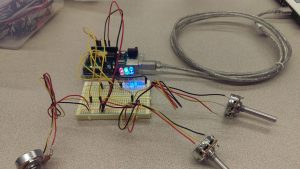
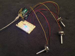
I used Arduino with three LEDs (red, blue and green) and 3 potentiometers. I edited the sketch code to control the red LED’s blinking speed and the brightness of green and blue LED with three different potentiometers .  The result, as shown in the image below, is quite as expected. The blinking speed of the red LED and the brightness of the green and blue LED is controlled by the plot sucessfully.

Components

  • 1 Arduino
  • 3 LED
  • 3 Resistor (220Ω)
  • 1 Breadboard
  • 3 Pots

Code

/*
 Analog Input
 Demonstrates analog input by reading an analog sensor on analog pin 0 and
 turning on and off a light emitting diode(LED) connected to digital pin 13.
 The amount of time the LED will be on and off depends on
 the value obtained by analogRead().

The circuit:
 * Potentiometer attached to analog input 0
 * center pin of the potentiometer to the analog pin
 * one side pin (either one) to ground
 * the other side pin to +5V
 * LED anode (long leg) attached to digital output 13
 * LED cathode (short leg) attached to ground

* Note: because most Arduinos have a built-in LED attached
 to pin 13 on the board, the LED is optional.

Created by David Cuartielles
 modified 20 Sep. 2016
 By Owen Hsiao

This example code is in the public domain.

http://www.arduino.cc/en/Tutorial/AnalogInput

*/

int sensorPin = A0; // select the input pin for the potentiometer
 //int bsensorPin = A1; // select the input pin for the potentiometer
 //int ledPin = 13; // select the pin for the LED
 int ledPin = 9;
 //int bledPin = 10;
 //int greenledPin = 11;
 int sensorValue = 0; // variable to store the value coming from the sensor
 //int bsensorValue = 0; // variable to store the value coming from the sensor

int potPin = A1; // Analog input pin that the potentiometer is attached to
 int potValue = 0; // value read from the pot

int potPin2 = A2; // Analog input pin that the potentiometer is attached to
 int pot2Value = 0; // value read from the pot
 int led = 10; // PWM pin that the LED is on. n.b. PWM 0 is on digital pin 10
 int led2 = 11; // PWM pin that the LED is on. n.b. PWM 0 is on digital pin 11

void setup() {
 // declare the ledPin as an OUTPUT:
 pinMode(ledPin, OUTPUT);
 // declare the bledPin as an OUTPUT:
 // pinMode(bledPin, OUTPUT);

// initialize serial communications at 9600 bps:
 Serial.begin(9600);
 // declare the led pin as an output:
 pinMode(led, OUTPUT);

// initialize serial communications at 9600 bps:
 Serial.begin(9600);
 // declare the led pin as an output:
 pinMode(led2, OUTPUT);
 }

void loop() {
 // read the value from the sensor:
 sensorValue = analogRead(sensorPin);
 // turn the ledPin on
 digitalWrite(ledPin, HIGH);
 // stop the program for <sensorValue> milliseconds:
 delay(sensorValue);
 // turn the ledPin off:
 digitalWrite(ledPin, LOW);
 // stop the program for for <sensorValue> milliseconds:
 delay(sensorValue);

potValue = analogRead(potPin); // read the pot value
 analogWrite(led, potValue/4); // PWM the LED with the pot value (divided by 4 to fit in a byte)
 Serial.println("hello"); // print the pot value back to the debugger pane
 delay(10); // wait 10 milliseconds before the next loop

pot2Value = analogRead(potPin2); // read the pot value
 analogWrite(led2, pot2Value/5); // PWM the LED with the pot value (divided by 4 to fit in a byte)
 Serial.println("hello"); // print the pot value back to the debugger pane
 delay(10); // wait 10 milliseconds before the next loop
 }
IMAG1134_BURST002 IMAG1135_BURST001

3 pots for 3 LEDs

Components

  • 1 Arduino
  • 1 breadboard
  • 3 LEDs (red, green, blue)
  • 3 potentiometers
  • 3 225-ohm resisters
  • wires

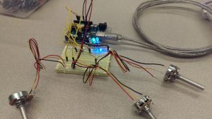
For this lab/hw, I controlled the brightness of each LED with a different potentiometer.

Code
// initialize pot pins
int potPin1 = A0;
int potPin2 = A2;
int potPin3 = A3;

// set pot values;
int potV1 = 0;
int potV2 = 0;
int potV3 = 0;

// initialize leds
int blueLed = 6;
int redLed = 9;
int greenLed = 11;

void setup() {
Serial.begin(9600);
// declare the led pin as an output:
pinMode(blueLed, OUTPUT);
pinMode(redLed, OUTPUT);
pinMode(greenLed, OUTPUT);
}

void loop() {
potV1 = analogRead(potPin1);
potV2 = analogRead(potPin1);
potV3 = analogRead(potPin1); // read the pot value
analogWrite(blueLed, potV1/4);
analogWrite(redLed, potV2/4);
analogWrite(greenLed, potV3/4);

delay(10); // wait a bit, for serial data
}


Lab 03 – Color Switcher

Description:

For this lab, I wanted to play around with all of the options available to me. I began with the pot controlling the blinking rate, then added a potentiometer to control the fade. After working through a minor issue with the digitalOut vs. analogOut that prevented the fade from working properly with the blinking, I was able to figure out how to make the two potentiometers play nice with each other.

Then I decided that I wanted to use the third potentiometer to control the mapping between the three LEDs—to use the rotation as a signal for which LED should be lit and which should be dark. So I added the third potentiometer and then did some research (and used the serial monitor) to read what values were being output by that new pot. I then set four increments, and had each individual LED light up for the first three (low values would be red, mid-low values would be green, mid-high values would be blue). Then I set the highest value to map to having all three LEDs lit at the same time. By using the serial monitor to troubleshoot from the beginning, I was able to get it to work with a minimum of trouble. So my first pot controls the blink rate, my second pot controls the fade level, and the third pot controls which LEDs are lit.

circuit board and LEDs

Components:

  • Arduino Uno
  • Breadboard
  • 3 potentiometers
  • 3 LEDs (red, green, blue)
  • 3 220Ω resistors
  • jumper wires
  • USB cable
  • computer

Code:


// EXTRA CREDIT CODE: mapping a third potentiometer so that I can control individual LEDs to fire one at a time,
// or have all three fire at once (when third pot is maxed out)

int fadepotPin = A1; // Analog input pin that the fade potentiometer is attached to
int fadepotValue = 0; // value read from the fade pot
int blinkpotPin = A0; // Analog input pin that the blink potentiometer is attached to
int blinkpotValue = 0; // value read from the blink pot
int mappingPin = A2; // this will be the one that maps rotation to LED color
int mappingValue = 0; // initially set the rotational mapping value to zero
int redledPin = 11;
int greenledPin = 10;
int blueledPin = 9;

void setup() {
// initialize serial communications at 9600 bps:
Serial.begin(9600);
// declare the led pins as output:
pinMode(redledPin, OUTPUT);
pinMode(blueledPin, OUTPUT);
pinMode(greenledPin, OUTPUT);
}

void loop() {
fadepotValue = analogRead(fadepotPin); // read the fade pot value
blinkpotValue = analogRead(blinkpotPin); // read the blink pot value
mappingValue = analogRead(mappingPin); // read the value on the mapping pot

// turn on only the LED(s) that correspond to the value of the third pot
// minimum value for blue, middle values for green, and max value for red
// then that will turn on the LEDs according to the fade value and blink value

// print the results to the serial monitor:
Serial.print("mappingValue = ");
Serial.print(mappingValue);
Serial.print("\n");

if (mappingValue < 255) { analogWrite(redledPin, fadepotValue/4); // PWM the LED with the pot value (divided by 4 to fit in a byte) delay(blinkpotValue); // delay by the blink pot value in milliseconds digitalWrite(redledPin, LOW); // then blink the LEDs off } else if (mappingValue >= 255 and mappingValue <; 610) { analogWrite(greenledPin, fadepotValue/4); // PWM the LED with the pot value (divided by 4 to fit in a byte) delay(blinkpotValue); // delay by the blink pot value in milliseconds digitalWrite(greenledPin, LOW); // then blink the LEDs off } else if (mappingValue >= 610 and mappingValue < 770) { analogWrite(blueledPin, fadepotValue/4); // PWM the LED with the pot value (divided by 4 to fit in a byte) delay(blinkpotValue); // delay by the blink pot value in milliseconds digitalWrite(blueledPin, LOW); // then blink the LEDs off } else if (mappingValue >= 770) {
analogWrite(redledPin, fadepotValue/4); // PWM the LED with the pot value (divided by 4 to fit in a byte)
analogWrite(blueledPin, fadepotValue/4);
analogWrite(greenledPin, fadepotValue/4);
delay(blinkpotValue); // delay by the blink pot value in milliseconds
digitalWrite(redledPin, LOW); // then blink the LEDs off
digitalWrite(blueledPin, LOW);
digitalWrite(greenledPin, LOW);
}
delay(blinkpotValue); // pause before blinking back on (also allows loop to run and pots to be adjusted)
}