RR6 – VR and Mixed Reality

1) I particularly liked the feedback through the hand paddles. It was unexpected and really enriched the experience (opening drawers, pulling handles, etc.). As mentioned in the Magic Leap article, some other VR experiences give feedback through vests or clothes – maximizing the number of senses involved (while maintaining continuity between them) could be really interesting. I also felt like certain architectural features in the environments took advantage of being able to place the user in them (overhead beams and ledges, for example) that wouldn’t work as well for traditional displays.

2) At one point, I ended up on the menu screen (pressing a wrong button?) and didn’t know how to navigate it. This issue seems hardly specific to VR, but it felt like a stronger clashing of worlds in VR, maybe because I have the expectation that is should be seamless (have as few distractions from the VR space as possible). I found it similarly challenging to figure how to use the hand paddles – do the different buttons have consistent functions across environments? Finally, I wear glasses, and while I could see without them, the blurriness somewhat detracted from the experience. I imagine this is a widespread issue, and I’m curious what’s been done for it.

Crawler (in circles) bot

Description

So my bot crawls, though mainly in circles (I believe the legs aren’t quite even). I tried to model my bot after knees, which are rigid in one direction (providing push) but bend in the other direction (to avoid undoing forward motion). I used binder clips to stabilize the bot’s base (the servo box) and prop the servo motor at a helpful angle.

Components

  • Arduino UNO
  • Servo motor
  • hookup wires
  • binder clips (1 very large, 1 small)
  • cardboard, popsicle sticks, wood glue, tape, pipecleaners

Code

/* Sweep
by BARRAGAN <http://barraganstudio.com>
This example code is in the public domain.

modified 8 Nov 2013
by Scott Fitzgerald
http://www.arduino.cc/en/Tutorial/Sweep
*/

#include ;

Servo myservo; // create servo object to control a servo
// twelve servo objects can be created on most boards

int pos = 0; // variable to store the servo position

void setup() {
myservo.attach(7); // attaches the servo on pin 9 to the servo object
}

void loop() {
for (pos = 0; pos <= 180; pos += 1) { // goes from 0 degrees to 180 degrees
// in steps of 1 degree
myservo.write(pos); // tell servo to go to position in variable 'pos'
delay(4); // waits 15ms for the servo to reach the position
}
delay(200);
for (pos = 180; pos >= 0; pos -= 1) { // goes from 180 degrees to 0 degrees
myservo.write(pos); // tell servo to go to position in variable 'pos'
delay(4); // waits 15ms for the servo to reach the position
}
delay(200);
}

Images/Video

knees   overview-shot  prop-detailcrawler-bot-video

(attempt at) Oscillating Fan

Description

I wanted to make a fan that fights with its on/off switch (hence oscillating between on and off). I envisioned a balance-based switch (the paper shape) on top of a force meter. To turn on the fan, you balance the switch on the FSR. The fan turns on, but the breeze it produces pushes the switch off balance, turning the fan off. The switch then comes back to balance, turning the fan on again (and so it continues). A pot is used to control the fan speed.

Issues:

  1. I tried a few fan designs (paper pin-wheel, plastic bottle), but couldn’t get it to produce a strong enough breeze to tip the switch off balance, even at the max pot value. I suspect the blades were slipping on the motor shaft, but I wasn’t willing to glue to it directly.
  2. It was challenging to make switch heavy enough to trip the force sensor while still light enough to be tipped off balance. I would try a photosensor next time (mine are currently encased in my last project).

Components

  • Arduino
  • pot, FSR, DC motor, battery pack
  • resistors and hookup wires
  • paper (and plastic bottle).

Code

/*
* one motor (speed controlled by pot) turns on in response to
* force applied by a weighted sail. a fan on the motor blows the
* sail, removing the force. I didn't implement the lights.
*
* modified version of AnalogInput
* by DojoDave <http://www.0j0.org>
* http://www.arduino.cc/en/Tutorial/AnalogInput
* Modified again by dave
*/

int potPin = A0; // pot input pin
int forcePin = A1; // FSR input pin
int motorPin = 9; // motor pin

int redPin = 12;
int bluePin = 11;

int potVal = 0; // store the value coming from the pot
int forceVal = 0; // store the value coming from the FSR

void setup() {
pinMode(redPin, OUTPUT);
pinMode(bluePin, OUTPUT);

Serial.begin(9600);
}
void loop() {
potVal = analogRead(potPin); // read the pot value, between 0 - 1024
forceVal = analogRead(forcePin); // read the FSR value

digitalWrite(redPin, LOW);
digitalWrite(bluePin, LOW);

Serial.print("pot value: ");
Serial.println(potVal);
Serial.print("FSR value: ");
Serial.println(forceVal);

if (forceVal > 200) {
analogWrite(motorPin, potVal/4); // turn on the motor. analogWrite ranges 0-255
digitalWrite(redPin, HIGH);
digitalWrite(bluePin, LOW);
}
else {
analogWrite(motorPin, 0); // turn off the motor
digitalWrite(redPin, LOW);
digitalWrite(bluePin, HIGH);
}

delay(500);
}

Images

fan-pic

fan_video

Bicycle accessories

bike-lock-rest helmet-rest-2

I recognized a trio of “thoughtless acts” around bicycles in my home. On top, I tend to store my bike cable by hanging in on my handlebars. In the middle image, handlebars are again used for storage, here by hanging a helmet. And on the bottom, my bike seat is used to store my helmet, keeping it attached to the bike (it’s clipped around the seat-post) and also in the orientation as it would be worm (by propping it on the seat). I presume neither handlebars nor seats were designed as storage spaces , but the same features that make for good grips (here protruding or curved, hand-sized grips) also make for good hooks. And my bicycle seat, designed for sitting, happens also to be of the right proportions to mount my helmet (something going on there in human proportions?).

As far as design solutions, these inspired me to think of other ways to introduce multi-functionality to items designed for hands/seats. Perhaps the doorknob on a closet door could be grooved, encouraging users to hang their most-used items on the knob itself instead of inside the closet, with similar adaptations for drawer or cabinet pulls.

The bike-seat storage seems harder to replicate elsewhere; it works because I only sit on the bike when I am also wearing the helmet (the thing stored on the seat). The same can’t be said for most seats.

Lab 5: Reactive Flower

Description

This rose responds to specific interactions. When a bug lands near the bloom, it turns on, pulsing white light. When a face comes near to the leaf (giving CO2), it calmly pulses blue light. And if you try to pick the flower, squeezing the base of the stem with moderate pressure, it flashes red light. At higher pressure, this flashing is accompanied by a blaring warning sound.

Components

  • Arduino
  • Breadboard
  • 2 photosensors
  • 1 force sensitive resistor (FSR)
  • 1 red, 1 blue, and 1 white LED
  • 1 piezo speaker
  • hookup wires
  • paper, straws, tape

Code

/*
controls various inputs and output to an origami flower
By Leah Rosenbaum
*/

int pullSensor = A0; // force sensor at the base of the stem
int bugSensor = A2; // photo sensor for presense of bug on the calyx
int proximitySensor = A1; // photo sensor for proximity of face to leaf

// select the pins for LED output:
int redPin = 11;
int whitePin = 9;
int bluePin = 10;
int piezoPin = 7;

int pullValue = 0; // stores value coming from the pull/force sensor
int bugValue = 0; // stores value coming from the photo/bug sensor
int proximityValue = 0; // stores value coming from the photo/proximity sensor

void setup() {
// declare the ledPin as an OUTPUT:
pinMode(redPin, OUTPUT);
pinMode(bluePin, OUTPUT);
pinMode(whitePin, OUTPUT);
pinMode(piezoPin, OUTPUT);

Serial.begin(9600);
}

void loop() {
digitalWrite(piezoPin, LOW);

pullValue = analogRead(pullSensor); // read the value from the force sensor
bugValue = analogRead(bugSensor); // read the value from the photo/bug sensor
proximityValue = analogRead(proximitySensor); // read in the value from the photo/proximity sensor

Serial.print("pull value:");
Serial.println(pullValue);
Serial.print("bug value:");
Serial.println(bugValue);
Serial.print("proximity value:");
Serial.println(proximityValue);

if ( pullValue > 700) { //if pulling too hard on the stem
allOff();

//flash the red LED and buzz piezo:
digitalWrite(redPin, HIGH); //turn on red LED
buzzPiezo(1000);
delay(25);

digitalWrite(redPin, LOW); //turn off red LED
buzzPiezo(1000);
delay(25);
}
else if (pullValue > 500) { //touching the stem
allOff();

//flash the red LED:
digitalWrite(redPin, HIGH);
delay(150);
digitalWrite(redPin, LOW);
delay(150);
}
else { //minimal force input
if (proximityValue < 800){ //and proximity to leaf
allOff();

//pulse blue:
fadePin(bluePin, 15, 30);
}
else { //minimal proximity input
if (bugValue < 900){
allOff();

//pulse the white LED:
fadePin(whitePin, 5, 30);
}
}
}
delay(500);
}

void buzzPiezo(int delayTime){
for( int i=0; i<250; i++ ) { // play it for 50 cycles
digitalWrite(piezoPin, HIGH);
delayMicroseconds(delayTime);
digitalWrite(piezoPin, LOW);
delayMicroseconds(delayTime);
}
}

void fadePin(char pinName, int fadeStep, int waitTime){
// fade in from min to max in increments of 5 points:
for (int fadeValue = 0 ; fadeValue <= 255; fadeValue += fadeStep) {
analogWrite(pinName, fadeValue);
delay(waitTime); // wait to see the dimming effect
}
for (int fadeValue = 255 ; fadeValue >= 0; fadeValue -= fadeStep) {
analogWrite(pinName, fadeValue);
delay(waitTime); // wait to see the dimming effect
}
}

void allOff(){
digitalWrite(redPin, LOW);
digitalWrite(bluePin, LOW);
digitalWrite(whitePin, LOW);
digitalWrite(piezoPin, LOW);
}

Images

responsive-flower

the everyday at large (changing scale)

At first I wasn’t sure if this was an example of industrial design, but Blauvelt includes the Airborne Snotty Vases and Buildings of Disaster as examples, so I figured it was worth thinking about. Growing up, our local frozen custard and burger place (it’s the Midwest…) featured a sculpture of a giant spoon and giant cherry (first image below). Though it was not the designer’s (or at least restaurant’s) intention, all the kids wanted to climb on the cherry and slide down the spoon (hence it was roped off). I remember liking it because it was a normal thing, but made really big and somehow that was fascinating, which I think is what Blauvelt’s “transforming the everyday” is about.

I remember feeling a similar fascination at a mundane thing made big when I saw the giant safety pin sculpture by Claes Oldenburg and Coosje van Bruggen at SF’s de Young museum (second image below). While also meant as an art piece, it reminded me of the spoon and cherry and made me think how “regular sized” objects could take on new functions if they were made bigger or smaller (the spoon could be a slide, the safety pin could be a lamp post). What function might an X serve if it was made really big/small, other than being an X for giant/ants? Some examples already exist: dinner forks and pitchforks, knives and swords, sewing pins and stakes/posts. It was interesting to note the common function of these tools, even if their use contexts are quite different.

giant-spoon-and-cherry giant-safety-pin

Lab 4: FSR Toothbrushing Indicator

Description

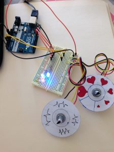
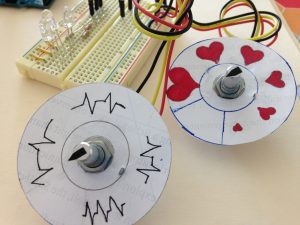
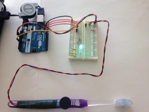
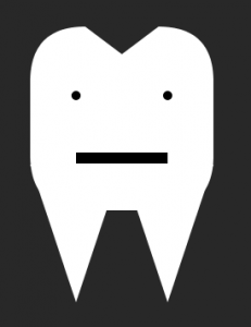
Brushing your teeth too lightly fails to remove plaque and debris, but brushing them too hard can harm the gums and strip tooth enamel. I used an Arduino, a force sensing resistor (FSR), and a toothbrush to indicate (roughly) appropriate force to apply when brushing your teeth. Too little pressure illuminates a green light, the right amount illuminates a blue light, and too much pressure illuminates a red light. The FSR data is also interpreted by Processing to depict either an underwhelmed, happy, or sad tooth (corresponding to too little, just right, and too much pressure, respectively).

Materials

  • Arduino UNO
  • Force sensing resistor (FSR)
  • toothbrush
  • breadboard, hookup wire, and resistors
  • LEDs
  • floral tape

Arduino Code

/*
send FSR values over a serial port
and set LED to corresponding brightness

By Leah Rosenbaum
*/

int forceSensor = A0; //input pin for the FSR
int bluePin = 11; // pins for LED output
int redPin = 9;
int greenPin = 10;

int forceValue = 0; // variable to store the value coming from the FSR

void setup() {
// declare the ledPin as an OUTPUT:
pinMode(bluePin, OUTPUT);
pinMode(greenPin, OUTPUT);
pinMode(redPin, OUTPUT);

Serial.begin(9600);
}

void loop() {
forceValue = analogRead(forceSensor); // read the value from the brightness sensor

//Serial.print("FSR value:");
Serial.println(forceValue);

if (0<= forceValue && forceValue < 400) {
digitalWrite(greenPin, HIGH);
digitalWrite(bluePin, LOW);
digitalWrite(redPin, LOW);
}
else if (320 <= forceValue && forceValue < 900){
digitalWrite(greenPin, LOW);
digitalWrite(bluePin, HIGH);
digitalWrite(redPin, LOW);
}
else {
digitalWrite(greenPin, LOW);
digitalWrite(bluePin, LOW);
digitalWrite(redPin, HIGH);
}

delay(500);
}

Processing Code

/* PROCESSING SKETCH
* Arduino Ball Paint
* (Arduino Ball, modified 2008)
* ----------------------
*
* Draw a tooth whose face corresponds
* to pressure exerted on a toothbrush
*
*/
import processing.serial.*;
// Change this to the portname your Arduino board
String portname = "/dev/cu.usbmodem1411"; // or "COM5"
Serial port;
String buf="";
int cr = 13; // ASCII return == 13
int lf = 10; // ASCII linefeed == 10

int serialVal = 0;
int width = 800;
int height = 800;

void setup() {
size(800,800);
frameRate(10);
smooth();
background(40,40,40);
noStroke();
port = new Serial(this, portname, 9600);
}

void draw() {
// erase the screen
background(40, 40, 40);

// draw the tooth
fill(255,255,255);
// main rectangle
rect(width*3/8, height*3/8, width/4, height/4, 60);
// the top divot
fill(40,40,40);
triangle(width*3/8 + 60, height*3/8, width*5/8 - 60, height*3/8, width/2, height*3/8 + 30);
//the roots
fill(255,255,255);
triangle(width*3/8, height*9/16, width/2, height*9/16, width*7/16, height*3/4);
triangle(width/2, height*9/16, width*5/8, height*9/16, width*9/16, height*3/4);

//according to the pressure (serial input), give a face
fill(0, 0, 0);
//eyes
ellipse(width*7/16, height*15/32, 10, 10);
ellipse(width*9/16, height*15/32, 10, 10);
//mouth, depending on pressure;
//not enough pressure (flat mouth)
if (serialVal < 400) {
fill(0, 0, 0);
rect(width*7/16, height*35/64, width/8, height/64);
}
// good pressure (smile)
else if (serialVal < 900) {
fill(255, 0, 0);
arc(width/2, height*35/64, width/8, height/10, 0, PI);
}
// too much pressure (frown)
else {
fill(255, 0, 0);
arc(width/2, height*37/64, width/8, height/10, PI, 2*PI);
fill(255, 255, 255);
arc(width/2, height*37/64, width/8, height/15, PI, 2*PI);
}
}

// called whenever serial data arrives
void serialEvent(Serial p) {
int c = port.read();
if (c != lf && c != cr) {
buf += char(c);
}
if (c == lf) {
serialVal = int(buf);
println("val="+serialVal);
buf = "";
}
}

setup

too-little-pressure  thats-great  too-much-pressure


RR4 – Ambient Time?

I’d be curious about an ambient display of time, particularly one with a medium notification level. It seems like many systems we currently use for time are either low notification level (user poll – I must look to a watch, phone, wall clock, etc. to read off the time) or high notification level (my phone buzzes/a notification pops up on my computer alerting me of an impending meeting). I suppose sunlight could be considered the original ambient information system for time, but how might we increase the granularity of information displayed or make it accessible indoors? There’s also the question of if we’re conveying time (the hour/minutes in a day) vs schedule (time until your next meeting/class/assignment).

Lab 3: LED Pulses

Description

This program fades three LEDs to a brightness determined by one potentiometer with a pause between fades determined by another potentiometer. The overall effect is intended to mimic pules/heartbeats, where the brightness could be analogous to beat strength and the pause time analogous to beat rate.

I interpreted the “mapping between the rotational position pot and LED output” to mean a map between the potentiometers’ visual configurations and the output (perhaps a misinterpretation – I’ll find out!), so I made two gauges to fit over the pots. On one gauge, the size of the heart corresponds to beat strength (the max brightness in the pulse) while on the other gauge, the rate diagrams of variable spaces are intended to convey the idea of slower or faster pulses.

Components

  • Arduino UNO board
  • 1 red, 1 green, and 1 blue LED
  • connector wires
  • 2 potentiometers
  • paper
  • markers
  • tape

Code

/*
LEDs are faded up to a brightness determined by one sensor at a rate (frequency)
determined by the other.
*/
int speedSensor = A0; //input pin for the speed potentiometer (how fast)
int brightSensor = A2; //input pin for the brightness potentiometer (how bright)
// select the pins for LED output:
int redPin = 9;
int greenPin = 10;
int bluePin = 11;
int speedValue = 0; //variable to store the value coming from the speed sensor
int brightValue = 0; //variable to store the value coming from the brightness sensor

void setup() {
// declare the ledPin as an OUTPUT:
pinMode(redPin, OUTPUT);
pinMode(greenPin, OUTPUT);
pinMode(bluePin, OUTPUT);
}

void loop() {
speedValue = analogRead(speedSensor); // read the value from the speed sensor
brightValue = analogRead(brightSensor); // read the value from the brightness sensor

//if the brightness is too low, there will be no steps calculated:
if(brightValue<80)
brightValue = 80;

/* fade in from min to max. To keep the same number of increments,
increment fadeValue by brightValue/80 */
for (int fadeValue = 0 ; fadeValue <= brightValue/4; fadeValue += brightValue/80) { 
// sets the value (range from 0 to brightValue/4): 
analogWrite(redPin, fadeValue); 
analogWrite(greenPin, fadeValue); 
analogWrite(bluePin, fadeValue); 
// wait to see the dimming effect:
 delay(10); 
} 
/* fade out from max to min. To keep the same number of increments,
increment fadeValue by brightValue/80 */ 
for (int fadeValue = brightValue/4 ; fadeValue >= 0;  fadeValue -= brightValue/80) {
// sets the value (range from 0 to brightValue/4):
analogWrite(redPin, fadeValue);
analogWrite(greenPin, fadeValue);
analogWrite(bluePin, fadeValue);
// wait to see the dimming effect:
delay(10);
}
//depending on the math, the min may not be 0. set pins to 0 for the long delay:
analogWrite(redPin, 0);
analogWrite(greenPin, 0);
analogWrite(bluePin, 0);

//wait for a time determined by the speed analog input:
delay(speedValue/1.5);
}

setup scale detail

Uncertainty on definition of TUI, particularly on input events

This line of thought started from the response prompt, I promise.

For the first reading response, I mentioned Swype typing available on touch screens. Seeing Fishkin’s categorization of traditional keyboards as distant (along the embodiment axis) and none (along the metaphor axis), I though that typing on a touch screen might change the embodiment level to full (the input device is the output device) or maybe near (if we consider the display part of the touchscreen to be different from where the keyboard appears).

But then I started to wonder if a touch screen is even a TUI according to their definition, my main point of uncertainty being the nature of the input event. Fishkin defines an input event as “a physical manipulation performed by a user with their hands on some ‘everyday physical object,’ such as tilting, shaking, squeezing, pushing, or, most often, moving.” Does moving a finger on a touch screen count as a physical manipulation if no object is moved around? Would writing with a stylus be considered more of an input event because, in that case, the user is moving an object? What about gesture-capture systems where there is no “everyday physical object” other than our own bodies? Maybe that’s the center of my question: do our own bodies count as “everyday physical objects” around which TUIs can develop (without a non-corporeal intermediary)?