
Description:
For this lab, I wanted to play around with all of the options available to me. I began with the pot controlling the blinking rate, then added a potentiometer to control the fade. After working through a minor issue with the digitalOut vs. analogOut that prevented the fade from working properly with the blinking, I was able to figure out how to make the two potentiometers play nice with each other.
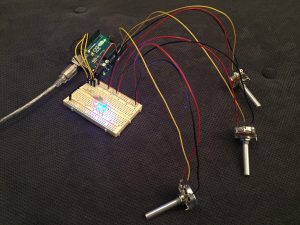
Then I decided that I wanted to use the third potentiometer to control the mapping between the three LEDs—to use the rotation as a signal for which LED should be lit and which should be dark. So I added the third potentiometer and then did some research (and used the serial monitor) to read what values were being output by that new pot. I then set four increments, and had each individual LED light up for the first three (low values would be red, mid-low values would be green, mid-high values would be blue). Then I set the highest value to map to having all three LEDs lit at the same time. By using the serial monitor to troubleshoot from the beginning, I was able to get it to work with a minimum of trouble. So my first pot controls the blink rate, my second pot controls the fade level, and the third pot controls which LEDs are lit.
Components:
- Arduino Uno
- Breadboard
- 3 potentiometers
- 3 LEDs (red, green, blue)
- 3 220Ω resistors
- jumper wires
- USB cable
- computer
Code:
// EXTRA CREDIT CODE: mapping a third potentiometer so that I can control individual LEDs to fire one at a time,

// or have all three fire at once (when third pot is maxed out)
int fadepotPin = A1; // Analog input pin that the fade potentiometer is attached to
int fadepotValue = 0; // value read from the fade pot
int blinkpotPin = A0; // Analog input pin that the blink potentiometer is attached to
int blinkpotValue = 0; // value read from the blink pot
int mappingPin = A2; // this will be the one that maps rotation to LED color
int mappingValue = 0; // initially set the rotational mapping value to zero
int redledPin = 11;
int greenledPin = 10;
int blueledPin = 9;
void setup() {
// initialize serial communications at 9600 bps:
Serial.begin(9600);
// declare the led pins as output:
pinMode(redledPin, OUTPUT);
pinMode(blueledPin, OUTPUT);
pinMode(greenledPin, OUTPUT);
}
void loop() {
fadepotValue = analogRead(fadepotPin); // read the fade pot value
blinkpotValue = analogRead(blinkpotPin); // read the blink pot value
mappingValue = analogRead(mappingPin); // read the value on the mapping pot
// turn on only the LED(s) that correspond to the value of the third pot
// minimum value for blue, middle values for green, and max value for red
// then that will turn on the LEDs according to the fade value and blink value
// print the results to the serial monitor:
Serial.print("mappingValue = ");
Serial.print(mappingValue);
Serial.print("\n");
if (mappingValue < 255) {
analogWrite(redledPin, fadepotValue/4); // PWM the LED with the pot value (divided by 4 to fit in a byte)
delay(blinkpotValue); // delay by the blink pot value in milliseconds
digitalWrite(redledPin, LOW); // then blink the LEDs off
}
else if (mappingValue >= 255 and mappingValue <; 610) {
analogWrite(greenledPin, fadepotValue/4); // PWM the LED with the pot value (divided by 4 to fit in a byte)
delay(blinkpotValue); // delay by the blink pot value in milliseconds
digitalWrite(greenledPin, LOW); // then blink the LEDs off
}
else if (mappingValue >= 610 and mappingValue < 770) {
analogWrite(blueledPin, fadepotValue/4); // PWM the LED with the pot value (divided by 4 to fit in a byte)
delay(blinkpotValue); // delay by the blink pot value in milliseconds
digitalWrite(blueledPin, LOW); // then blink the LEDs off
}
else if (mappingValue >= 770) {
analogWrite(redledPin, fadepotValue/4); // PWM the LED with the pot value (divided by 4 to fit in a byte)
analogWrite(blueledPin, fadepotValue/4);
analogWrite(greenledPin, fadepotValue/4);
delay(blinkpotValue); // delay by the blink pot value in milliseconds
digitalWrite(redledPin, LOW); // then blink the LEDs off
digitalWrite(blueledPin, LOW);
digitalWrite(greenledPin, LOW);
}
delay(blinkpotValue); // pause before blinking back on (also allows loop to run and pots to be adjusted)
}