The Jukebox

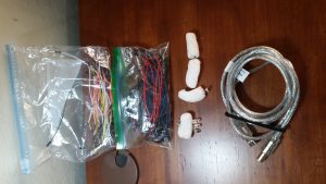
We created a musical instrument that focuses on manipulating MIDI files.

The basic idea of the instrument is to enable users to play musical variations of songs in almost infinite combinations of tempo, attack, decay and release.

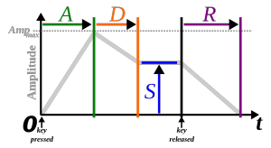
Three potentiometers correlate to three transformations based on ASDR, which stands for attack, sustain, decay and release. We altered the attack decay and release which allowed a person using the device to create the variations.

  • Attack time is the time taken for initial run-up of level from nil to peak, beginning when the key is first pressed. We mapped 1024 values of the potentiometer to 0 – 1.5s.
  • Decay time is the time taken for the subsequent run down from the attack level to the designated sustain level. We mapped 1024 values of the potentiometer to 0-1.5s.
  • Sustain level is the level during the main sequence of the sound’s duration, until the key is released. We kept this constant at 1.5
  • Release time is the time taken for the level to decay from the sustain level to zero after the key is released. We mapped 1024 values of the potentiometer to 0-1.5s.
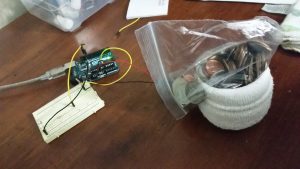
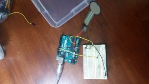
1100px-adsr_parameter-svg

Code:


/*
Logic used:
1. Set a MIDI playback with set envelope
2. Store a recorded fragment and loop over the recorded fragment
Original Authors: Multiple contributors to Minim
New authors: Neera Grover, Vivian Liu, Sandeep Pal and Ganesh Iyer
*/
import ddf.minim.*;
import ddf.minim.ugens.*;
import javax.sound.midi.*;
Minim minim;
// Sequencer objects – one for base and one for loop
Sequencer base;
Sequencer loop;
Sequence baseSequence;
Sequence backingLoop;
// For recording loops
AudioInput loopIn;
AudioRecorder loopRecorder;
// For playback
AudioOutput out;
AudioPlayer player;
import processing.serial.*;
import cc.arduino.*;
Arduino arduino;
int ledPin = 13;
int val;
int val1;
int val2;
int val3;
int val4;
void setup(){
size(512, 200, P3D);
minim = new Minim(this);
/**Connecting arduino to Processing.*/
arduino = new Arduino(this, Arduino.list()[1], 57600);
arduino.pinMode(ledPin, Arduino.OUTPUT);
arduino.pinMode(0, Arduino.INPUT); //(A0=0)
// need to set variable loopIn to something that records or reuses a sample
// right now, the issue is that it always picks up what the microphone records
loopIn = minim.getLineIn();
// getLineIn seems to be the biggest problem
// How does one use the audio generated by the computer itself as a fragment to loop over?
// enable monitoring seems to do absolutely nothing for this cause. causes feedback. some interesting sound though.
loopIn.disableMonitoring();
loopRecorder = minim.createRecorder(loopIn, currentLoop.wav);
// out is playing the minim object back to us
out = minim.getLineOut(Minim.MONO);
try
{
// get a disconnected sequencer. this should prevent
// us from hearing the general midi sounds the
// sequecer is automatically hooked up to.
base = MidiSystem.getSequencer( false );
// have to open it
base.open();
// load our sequence
baseSequence = MidiSystem.getSequence( createInput( bach.midi ) );
// put it in the sequencer
base.setSequence( baseSequence);
// hook up an instance of our Receiver to the Sequencer’s Transmitter
base.getTransmitter().setReceiver( new MidiReceiver() );
base.setTickPosition(10000);
base.setLoopEndPoint(20000);
// just keep looping
//base.setLoopCount( Sequencer.LOOP_CONTINUOUSLY );
// and away we go
// Hello Vivian!
base.start();
}
catch( MidiUnavailableException ex ) // getSequencer can throw this
{
// oops there wasn’t one.
println( No default sequencer, sorry bud. );
}
catch( InvalidMidiDataException ex ) // getSequence can throw this
{
// oops, the file was bad
println( The midi file was hosed or not a midi file, sorry bud. );
}
catch( IOException ex ) // getSequence can throw this
{
println( Had a problem accessing the midi file, sorry bud. );
}
}
class MidiReceiver implements Receiver
{
void close() {}
void send( MidiMessage msg, long timeStamp )
{
// we only care about NoteOn midi messages.
// here’s how you check for that
if ( msg instanceof ShortMessage )
{
ShortMessage sm = (ShortMessage)msg;
// if you want to handle messages other than NOTE_ON, you can refer to the constants defined in
// ShortMessage: http://docs.oracle.com/javase/6/docs/api/javax/sound/midi/ShortMessage.html
// And figure out what Data1 and Data2 will be, refer to the midi spec: http://www.midi.org/techspecs/midimessages.php
if ( sm.getCommand() == ShortMessage.NOTE_ON )
{
// note number, between 1 and 127
int note = sm.getData1();
// velocity, between 1 and 127
int vel = sm.getData2();
// we could also use sm.getChannel() to do something different depending on the channel of the message
// see below the draw method for the definition of this sound generating Instrument
out.playNote( 0, 0.1f, new Synth( note, vel ) );
}
}
}
}
class Synth implements ddf.minim.ugens.Instrument
{
Oscil wave;
Damp env;
int noteNumber;
Synth( int note, int velocity )
{
noteNumber = note;
float freq = Frequency.ofMidiNote( noteNumber ).asHz();
float amp = (float)(velocity1) / 126.0f;
wave = new Oscil( freq, amp, Waves.QUARTERPULSE );
// Damp arguments are: attack time, damp time, and max amplitude
env = new Damp( 0.01f, 0.5f, 1.0f );
// writing code for looping
wave.patch( env );
}
void noteOn( float dur )
{
// make sound
env.activate();
env.patch( out );
}
void noteOff()
{
env.unpatchAfterDamp( out );
}
}
void draw(){
val = arduino.analogRead(0);
val1 = arduino.analogRead(1);
val2 = arduino.analogRead(2);
val3 = arduino.analogRead(3);
val4 = arduino.analogRead(4);
// set the tempo
if ((val/4) < 250)) {
base.setTempoInBPM( val/4 );
}
base.setLoopCount(val2 % 10);
//set loops
//base.startRecording();
println(base.getLoopCount());
println(base.getLoopEndPoint());
println(base.getLoopStartPoint());
println(val1 * 8);
println(base.getTickPosition());
//loopcount isn’t working out
//if we get above the tick position of 20000, go back to 10000 and play again
if ((base.getTickPosition()) > 20000 (val1 * 8)) {
base.setTickPosition(10000);
//base.stopRecording();
}
// Code snippet to draw waves
background(0);
stroke(255);
// draw the waveforms
// the values returned by left.get() and right.get() will be between -1 and 1,
// so we need to scale them up to see the waveform
for(int i = 0; i < loopIn.left.size()1; i++)
{
line(i, 50 + loopIn.left.get(i)*50, i+1, 50 + loopIn.left.get(i+1)*50);
line(i, 150 + loopIn.right.get(i)*50, i+1, 150 + loopIn.right.get(i+1)*50);
}
// end code snippet to draw waves
}

TUI Final Project proposal – Brushee

Members: Mudit, Adam and Neera

We intend to continue working on Brushee as per the mid-term project proposal. Additionally, based on the feedback after the mid-term project proposal presentations, here are a few aspects we will strive to build upon  –

1)     We plan to stick to our original scope of encouraging pre-linguistic children to brush their teeth. We will not be focusing on the technique they use for brushing their teeth.

2)     In addition, we will focus on fleshing out the interaction to sustain routine. As we heard in feedback and also had an opportunity to observe (although very limited) that the age group of kids we are focusing on, get bored of the same routine very quickly. In order to address that and keep them engaged, we will be working on the same character doing different things everyday and even characters changing over time e.g Elmo appearing on the screen from different directions, Elmo appearing with Abby, Bob train appearing instead of Elmo/Abby etc.

3)      Furthermore, we strive to keep the interaction really simple, so that we do not overwhelm the child and distract him away from the main task of brushing. Some initial interaction design details are illustrated in the sketch below –

  • Elmo emerges from one corner of the mirror as soon as the child picks up the brush
  • Elmo  greets the child with a welcome message like, “Hey, good morning. Let’s put some toothpaste on the brush  and start brushing!”
  • Following the child’s cue, Elmo takes out a brush and starts brushing, with a pleasant background score
  • Elmo takes the child through a 3 minute routine which involves brushing teeth and gums, spitting, and finally, rinsing the mouth. Anytime during the 3 minutes, if the child stops brushing, Elmo becomes sad and prompts the child to continue brushing.
  • After the 3 minutes are over, Elmo congratulates the child and invites the child to pose for a picture with him. Next, the laptop/tablet’s front camera comes on and captures the face of the child and creates a snapshot of Elmo and the child side by side.
  • This snapshot is the child’s reward for brushing and is stored in memory. The child can accrue a streak of snapshots and subsequently get to unlock new characters.

4)     On the hardware front, we will be using an accelerometer instead of the tilt sensor as the data stream we were getting as output from the tilt sensor (comprised of 1s and 0s) is quite hard to map to the physical movement and process further downstream.

Materials Required to be Reserved: None

Single and Double Servo Crawlers

Ganesh and I worked on a proof of concept with one servo motor wherein we used a single wire to propel the servo forward.  The motion is illustrated in the video at the link –

https://drive.google.com/open?id=0ByHw8c_nutT2ZVZ6WllBbUJpOVk

After trying various mechanisms, we picked this one with two legs made out of a single wire. The key in this arrangement is that the two legs are of different lengths. This enables each leg to alternately anchor and drag the motor while also drifting slightly sideways and the next step correcting for the sideways drift.

After being successful with the single motor and the mechanism, we tried using two motors to propel a stuffed toy supported on chopsticks. The idea being that the two motors would work in opposite directions –  anchoring and propelling forward alternately (pic included below).

crawler


Code:


/*
* Servo Control Serial
* modified for TUI October 2007
* Servo Serial Better
* ——————-
*
* Created 18 October 2006
* copyleft 2006 Tod E. Kurt <tod@todbot.com>
* http://todbot.com/
*
* adapted from “http://itp.nyu.edu/physcomp/Labs/Servo”
*/

int servoPin1 = 7; // Control pin for servo motor
int servoPin2 = 8; // Control pin for servo motor

int pulseWidth = 0; // Amount to pulse the servo
long lastPulse = 0; // the time in millisecs of the last pulse
int refreshTime = 20; // the time in millisecs needed in between pulses
int val; // variable used to store data from serial port

int minPulse = 500; // minimum pulse width
int maxPulse = 2250; // maximum pulse width

void setup() {
pinMode(servoPin1, OUTPUT); // Set servo pin as an output pin
pinMode(servoPin2, OUTPUT); // Set servo pin as an output pin
pulseWidth = minPulse; // Set the motor position to the minimum
Serial.begin(9600); // connect to the serial port
Serial.println(“Servo control program ready”);
}

void loop() {
pulseWidth = (4 * (maxPulse-minPulse) / 8) + minPulse;
updateServo();
delay(1000);
pulseWidth = (8 * (maxPulse-minPulse) / 8) + minPulse;
updateServo();
delay(1000);
}
// called every loop().
// uses global variables servoPi, pulsewidth, lastPulse, & refreshTime
void updateServo() {
// pulse the servo again if rhe refresh time (20 ms) have passed:
if (millis() – lastPulse >= refreshTime) {
digitalWrite(servoPin1, HIGH); // Turn the motor on
digitalWrite(servoPin2, HIGH); // Turn the motor on
delayMicroseconds(pulseWidth); // Length of the pulse sets the motor position
digitalWrite(servoPin1, LOW); // Turn the motor off
digitalWrite(servoPin2, LOW); // Turn the motor off
lastPulse = millis(); // save the time of the last pulse
}
}

Rotating Pinwheel

For this lab, I built a pinwheel powered by the dc motor. While making the pinwheel wasn’t very hard, a lot of thought and effort went into controlling its stability and speed on the motor’s spindle. After a very few spins, the spindle makes the hole in the pinwheel bigger causing the pinwheel paper to lose contact with the motor which further results in loss of control over the motion of the pinwheel and the speed.

To circumvent the problem, I used a twist tie to harness the motion of the spindle and transfer it onto the pinwheel. The arrangement is depicted in the photo attached. I then hosted the pinwheel and motor on a candy holder to allow for the pinwheel to get enough space to spin. I also placed a sticker on the top of the spindle hole to prevent the paper pinwheel from flying away.

img_20161009_230825https://drive.google.com/a/berkeley.edu/file/d/0ByHw8c_nutT2LU9EcGRNMWR2b28/view?usp=sharing

Code:

/*
* one pot fades one motor
* modified version of AnalogInput
* by DojoDave <http://www.0j0.org>
* http://www.arduino.cc/en/Tutorial/AnalogInput
* Modified again by dave
*/

int potPin = 0; // select the input pin for the potentiometer
int motorPin = 9; // select the pin for the Motor
int val = 0; // variable to store the value coming from the sensor
void setup() {
pinMode(motorPin, OUTPUT);
Serial.begin(9600);
}
void loop() {
val = analogRead(potPin); // read the value from the sensor, between 0 – 1024
Serial.println(val);
analogWrite(motorPin, val/4); // analogWrite can be between 0-255
}

Thoughtless Act(s) : My TUI Kit

I found my thoughtless act in my TUI Kit. I have been using the styrofoam from the first lab for building diffusers to anchor my electronic components. As the pic indicates, I plug my leds, photocells and diodes into it to keep them organized and keep myself from rummaging through the entire box when I need them. I also packed away my resistors in a small ziploc to keep them from running loose inside the box which used to give me a hard time finding them. I use a hair tie to keep my Arduino wire manageable. I have separated my circuit building (colored) wires from the ground and power wires to save some time in pulling out wires.


I hadn’t put much thought into most of these acts except for separating the wires based on color and only realized the rest of them when I started looking around for thoughtless acts. Going through my own thoughtless acts and those of others (on the various resources like Flickr, IDEO website, Pinterest etc on the class website), I have realized the importance of noticing people’s thoughtless acts and using them as inspiration during the design process. Taking this thought forward, if I were a designer designing a TUI kit for myself I would have made the solution better by using a sectioned box wherein each section would be customized in size and shape for the component that it would hold. I would also include important information like resistor color coding on the lid for easy access.

20161008_170423 20161008_170433 20161009_164400

Halloween Candy Meter

For this lab, I decided to make a Halloween Candy meter that I will be needing very soon as Halloween is around the corner. My community is a very enthusiastic about trick or treating and as a result of that kids are able to amass an amazing amount of candy. This ends up being a nightmare for the parents. Many a times they accompany their kids and start nagging them to stop when candy levels get too high. The kids obviously do not enjoy this experience of being shadowed around when they are having fun trick-o-treating with their friends.

I decided to use my Arduino kit to solve this problem. I used the FSR to sense the weight of candy collected and calibrated it such that –

  • it would start a blinking led when it is getting closer to a pound of candy
  • it would start beeping (using the piezo) when the weight of the collected candy got to the one-pound mark (signaling that it is time to go home)

After uploading my code into the Arduino, I encased the breadboard and the Arduino in a takeout deli box with the FSR sensor facing outward towards the candy. I then put the deli box in my daughter’s Halloween Jack o Lantern candy collector. The video below illustrates that –

https://drive.google.com/a/berkeley.edu/file/d/0ByHw8c_nutT2R2hCUzNVMEo3Sjg/view?usp=sharing

All I need to think about now is to put together a costume which is way more fun than nagging a toddler around on a fun trick-o-treating night!

Components – FSR, LED and Piezo

Code:

/*
* ——–
*
*
* Created 24 October 2006
* copyleft 2006 Tod E. Kurt &lt;tod@todbot.com
* http://todbot.com/
*/

int fsrPin = 0; // select the input pin for the potentiometer
int speakerPin = 7;
int ledPin = 13;

int fsrReading = 0;
int val = 0;

void setup() {
pinMode(speakerPin, OUTPUT);
pinMode(ledPin, OUTPUT);
Serial.begin(9600);
Serial.println(“ready”);
}

void loop() {

digitalWrite(speakerPin, LOW);

fsrReading = analogRead(fsrPin); // read value from the sensor
Serial.println(fsrReading);
val = fsrReading*2; // process the value a little
//val = val/2; // process the value a little

if (fsrReading < 10) {
Serial.println(” – No pressure”);
} else if (fsrReading < 100) {
Serial.println(” – Light squeeze”);
digitalWrite(ledPin, HIGH); // turn the LED on pin 13 on (HIGH is the voltage level)
delay(100); // wait for a second
digitalWrite(ledPin, LOW); // turn the LED on pin 13 off by making the voltage LOW
delay(100);
} else if (fsrReading < 400) {
Serial.println(” – Medium squeeze”);
} else {
Serial.println(” – Big squeeze”);
for( int i=0; i<500; i++ ) { // play it for 50 cycles
digitalWrite(speakerPin, HIGH);
delayMicroseconds(val);
digitalWrite(speakerPin, LOW);
delayMicroseconds(val);
}

}

}


Running Experience

Running shoes with gel technology have completely changed how I experience running. On one of my visits to the chiropractor, we started having a conversation about the importance of posture and balance for spine health. The chiropractor, an avid runner, shared his excellent experience with his new gel shoes and suggested that it might be a direction worth exploring.

After initial hesitance due to the priceyness, I gave it a shot and there has been absolutely no looking back. Little did I know that so much thought and research goes into understanding the running experience and tailoring technology to help improve the experience. Having had an exposure to a cargo-cult mockup would definitely not have convinced me. I would have doubted the claims made by a gel insertions and stretchable fabric no matter how well explained. Even the gizmodo video below would have had a hard time convincing me –

http://www.gizmodo.com.au/2015/04/2-technologies-you-didnt-know-existed-in-running-shoes/


It is only after actually experiencing it for myself did I realize how it felt when gel absorbed and dispersed the energy from the shock and prevented it from transmitting up to my back. As a result, I do not feel tired after long walk and runs.

In this context, Blauvelt’s Strangely Familiar: Design and Everyday Life resonated with me the most out of all the readings. It is very true in the case of my gel shoes that “design is both invisible and conspicuous, familiar and strange. It surrounds us while fading from view, becoming second nature and yet seemingly unknowable.”  

My back had improved a lot and I wear my Asics Gel Running shoes every single day and cannot imagine my long walks and runs without them. If I could have it my way, I would have this technology in all my shoes. 


Pot of Gold

For the programming part of the lab, I created a visualization which starts with a circle at the corner of the screen and a rectangle in the middle. As force is exerted on the FSR, the circle on the left corner starts travelling diagonally across the screen and the edges of the rectangle start rounding. At a point, the circle hides behind the rectangle as if it were a coin that went into a pot/jar.

This inspired mechanical part of my lab today. I used a pot to make contact with the FSR. Then I used a small ziploc bag full of coins to exert pressure on the FSR. The pressure could be measured by the number of quarters.

Arduino Sketch:

/* FSR testing sketch.

Connect one end of FSR to 5V, the other end to Analog 0.
Then connect one end of a 10K resistor from Analog 0 to ground
Connect LED from pin 11 through a resistor to ground

For more information see www.ladyada.net/learn/sensors/fsr.html */

int fsrAnalogPin = 0; // FSR is connected to analog 0
int LEDpin = 13; // connect Red LED to pin 11 (PWM pin)
int fsrReading; // the analog reading from the FSR resistor divider
int LEDbrightness;

void setup(void) {
Serial.begin(9600); // We’ll send debugging information via the Serial monitor
pinMode(LEDpin, OUTPUT);
}

void loop(void) {
fsrReading = analogRead(fsrAnalogPin);
//Serial.print(“Analog reading = “);
//Serial.println(fsrReading);

// we’ll need to change the range from the analog reading (0-1023) down to the range
// used by analogWrite (0-255) with map!
LEDbrightness = map(fsrReading, 0, 1023, 0, 255);
// LED gets brighter the harder you press
analogWrite(LEDpin, LEDbrightness);

delay(100);
Serial.println(fsrReading);
}

Processing Sketch:

/* PROCESSING SKETCH
* Arduino Ball Paint
* (Arduino Ball, modified 2008)
* ———————-
*
* Draw a ball on the screen whose size is
* determined by serial input from Arduino.
*
* Created 21 September 2016
* Noura Howell
*/
import processing.serial.*;
// Change this to the portname your Arduino board
String portname = “COM3″;
Serial port;
String buf=””;
int cr = 13; // ASCII return == 13
int lf = 10; // ASCII linefeed == 10

int serialVal = 0;

void setup() {
size(700,700);
frameRate(10);
smooth();
background(40,40,40);
//noStroke();
port = new Serial(this, portname, 9600);
}

void draw() {
// erase the screen
background(40, 40, 40);

// draw the ball
fill(255, 255, 255);
//ellipse(150,150,serialVal,serialVal);
ellipse(serialVal,serialVal,150,150);
rect(200, 300, 300, 300, serialVal,serialVal, serialVal, serialVal);
}

// called whenever serial data arrives
void serialEvent(Serial p) {
int c = port.read();
if (c != lf && c != cr) {
buf += char(c);
}
if (c == lf) {
serialVal = int(buf);
println(“val=”+serialVal);
buf = “”;
}
}20160927_23281420160927_212835


Mazda CX5 Dasboard (again :))

The Pousman and Stasko reading took me back to thinking about my car’s dashboard along the design dimensions of information capacity, notification level, representational fidelity and aesthetic emphasis (Posuman et al:69). It has a high information capacity displaying between 15-20 nuggets of information including the status of doors, seat belts, fuel tank, air pressure, next service due date etc. However, excellent execution along the dimensions of notification level, representational fidelity and to some extent aesthetic emphasis make the TUI very intuitive and pleasant to use.

The Notification Levels of the fuel tank are a very good example of this excellent execution. It visually indicates the amount of fuel in the fuel tank and the number of miles remaining in an unobtrusive way. When the fuel level starts falling below a certain level, the display of icon of the fuel tank turns yellow. If not refueled after a certain point the yellow fuel tank icon starts blinking and if continued unfueled, it turns red and adds a beep to grab my attention. The iconic fuel tank and the scale metaphor that displays fuel status make for a good Representational Fidelity. On the final dimension i.e. Aesthetic Emphasis, I think the TUI is more functional while still looking decent but might not score too high on artistic measures.

Last but not the least, I would have liked a well designed ambient system to monitor speed wherein, it would alert me in an attention grabbing style if I were going over or under the required speed limit of the road I am driving on. Additionally, it could make me aware in an unobtrusive way of the average speed of the general traffic on the road at that time. I think of all the dimensions of the ambient system design, the combination of notification level and representational fidelity requires the most thought from the designer to differentiate the functional smoothness of a TUI.

20160925_18245520160925_181602

Behavior Incentivizer

Project :
BIP! [Behavior Incentivizer Project] (Final Name TBD)

Team :
Adam Hutz, Mudit Kakkar, Neera Grover

Objective :
The key objective of this project is to build a Tangible User Interface for children who are in the early phases of language development. It should embody a rewards system,
and require actions from the child to achieve the reward. We aim to design intuitive
triggers to hook them into the interaction loop while also guiding behavior through cues and variable rewards to help inculcate positive habits.

Background :
It’s a challenge to communicate with kids who are in early linguistic or prelinguistic
phases of language development and do not always understand causality of everyday
activities. For instance, it is difficult to explain to a 2yearold that brushing their teeth and bathing everyday are essential for keeping hygiene. Similarly, sleep is an acquired behavior as well, something that children learn over a passage of time. Over the years,experts have delved deep into how children learn – and advanced techniques for patterns of potty training and sleep training. Most of these techniques aim at guiding the child’s behavior through cues, routines and rewards.
We feel that this project is at a unique intersection of behavior change, communication (non or early verbal), and education, all while serving a very specialized user group. It is particularly well suited to be a TUI as it is aimed at kids who aren’t savvy enough to use complicated apps.

Proposal :
BIP is placed in the child’s sleeping area with the intent to cue a sleep routine
1) The parent gives their child a prompt: say, to brush their teeth. Upon successful
completion of the task the adult might give the child a token .
2) The child feeds the token to the pet and the pet does a happy dance.
3) This can be repeated for as many tasks as needed and the tokens keep
collecting inside the toy.
4) The parent can remove them later and start over the next day.

habitcuereward-001-e1447002533148:

Constraints:

Hard to follow a user centred design process as it’s hard to get feedback from users of
this age.