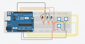
DJ Spectrumizer

Components
• 1 Arduino Uno
• 3 resistor (220 ohms)
• 3 potentiometers
• 3 LEDs (red, blue, green)
• 1 breadboard

Description
Welcome to DJ Spectrumizer. This lab project involves three potentiometers that control LEDs in three ways

  1. To control the color in the spectrum (Hue)
  2. To control the brightness of the light ( Vue)
  3. To control the rate at which they blink . (Beats)

Extra Credit :

A combination of these controls enables a person using the DJ Spectrumizer to set the mood of the party with the color and brightness and make the color blink based on the beats of the song he/she is playing.

I researched about the range of beats a song can have and found out that it ranges from 40bpm to 220bpm. I have used the potentiometer to map the values to this.

Code


// The three primary colour LEDs, driven as analgue outputs (actually PWM, but
// close enough for our analogue eyes).

const int ledPinRed = 11; // Red LED connected to analogue out pin
const int ledPinGrn = 10; // Green LED connected to analogue out pin
const int ledPinBlu = 9; // Blue LED connected to analogue out pin

// The Brightness potentiometer goes on an analogue pin, taking the pin from
// 0V to 5V.

const int potPinSat = 1;

// The Hue potentiometer goes on an analogue pin, taking the pin from
// 0V to 5V.

const int potPinHue = 2;

// The Beats potentiometer goes on an analogue pin, taking the pin from
// 0V to 5V.

const int potPinBeats = 3;

// Constants to define the ranges.

const int hueRedLow = 0;
const int hueRedHigh = 255;
const int hueBlue = 170;

// The size of the angle of one sector (1/6 of a colour wheel), and of a complete
// cycle of the colour wheel.

const int angleMin = 0;
const int angleSector = 60;
const int angleMax = 360;

const int brightMin = 0;
const int brightMax = 255;

//constants to define the range of beats
const int beatsMin = 40;
const int beatsMax = 220;

// Work variables.

// The hue potentiometer value is mapped to the range 0 to 360 (degrees).
int potValueHue;

//The brightness potentiometer value is mapped from 0 to 255 (full brightness)
int potValueSat;

//The beats potentiometer value is mapped from 40 to 220
int potValueBeats;

int hue, brightness;

const int saturation = 255;

// The brightess of each LED (0 to 255).

unsigned int r, g, b;

void setup() {
// Still need to set a baud rate, even for USB.
Serial.begin(9600);

// Set LED pins to output.
pinMode(ledPinRed, OUTPUT);
pinMode(ledPinGrn, OUTPUT);
pinMode(ledPinBlu, OUTPUT);

// Poteniometer analogue pin is an input.
pinMode(potPinHue, INPUT);
pinMode(potPinSat, INPUT);
pinMode(potPinBeats, INPUT);
}

void loop() {

// The Hue potentiometer value is mapped to degrees - 0 to 360 - for convenience.
potValueHue = map(analogRead(potPinHue), 0, 1023, angleMin, angleMax);
// The Brightness potentiometer value is mapped to values from 0 to 255.
potValueSat = map(analogRead(potPinSat), 0, 1023, brightMin, brightMax);
//The beats potentiometer value is mapped to values from 40 to 220 bpm
potValueBeats = map(analogRead(potPinBeats),0,1023, beatsMin,beatsMax);

// Colour wheel mode (red to red, wrapped around in a cycle).
hue = map(potValueHue, angleMin, angleMax, hueRedLow, hueRedHigh);
brightness = potValueSat;

// Do the conversion.
HSBToRGB(hue, saturation, brightness, &r, &g, &b);

analogWrite(ledPinRed, r);
analogWrite(ledPinGrn, g);
analogWrite(ledPinBlu, b);

// converting beats per minute to delay
int bpmToDelay = 1000 / (220/60);
delay(bpmToDelay);
}

// This function taken from here:
// http://eduardofv.com/read_post/179-Arduino-RGB-LED-HSV-Color-Wheel-

void HSBToRGB(
unsigned int inHue, unsigned int inSaturation, unsigned int inBrightness,
unsigned int *oR, unsigned int *oG, unsigned int *oB )
{
if (inSaturation == 0)
{
// achromatic (grey)
*oR = *oG = *oB = inBrightness;
}
else
{
unsigned int scaledHue = (inHue * 6);
unsigned int sector = scaledHue >> 8; // sector 0 to 5 around the color wheel
unsigned int offsetInSector = scaledHue - (sector << 8); // position within the sector unsigned int p = (inBrightness * ( 255 - inSaturation )) >> 8;
unsigned int q = (inBrightness * ( 255 - ((inSaturation * offsetInSector) >> 8) )) >> 8;
unsigned int t = (inBrightness * ( 255 - ((inSaturation * ( 255 - offsetInSector )) >> 8) )) >> 8;

switch( sector ) {
case 0:
*oR = inBrightness;
*oG = t;
*oB = p;
break;
case 1:
*oR = q;
*oG = inBrightness;
*oB = p;
break;
case 2:
*oR = p;
*oG = inBrightness;
*oB = t;
break;
case 3:
*oR = p;
*oG = q;
*oB = inBrightness;
break;
case 4:
*oR = t;
*oG = p;
*oB = inBrightness;
break;
default: // case 5:
*oR = inBrightness;
*oG = p;
*oB = q;
break;
}
}
}

potLab

Could not show it properly in a Video. Will demonstrate it in the class.

Mixed Reality ?!?!?

In Kenneth P. Fishkin’s, definition of taxonomy for Tangible User Interfaces, enough stress hasn’t been laid on an important aspect of interaction or the input i.e. the feedback aspect. We need to think about adding another dimension to the taxonomy. This could be based on how much humans perceive the interaction feedback(we could have partially perceived, fully perceived and not perceived categories).
Secondly I am not satisfied with the taxonomy as it limits the ways of interaction. Nowadays devices have started supporting other forms of interaction such as using eyes and brain waves. This dimension could be based on the different ways humans can sense or interact with an interface such as eyes, brain, speech.
The perfect example that comes to my mind to challenge the taxonomy would be Microsoft Hololens. When people wear the device, they see a sort of mixed-reality as there are objects seen that exist as well as objects that do not exist. So people can interact with virtual objects in the virtual world but gives a perception to the user as if the interaction is happening in the real world. Here, the feedback aspect is interesting as we want to know where should we actually categorize this experience because it would belong to all the embodiment types and almost all the metaphor types due to the mixed reality aspect. Hence we need to categorize this into perceivability. We would call this partially perceived as although we are able to see or hear things in the mixed world, we are still not able to touch it as we do not feel it.
In conclusion I would say that, although Fishkin’s article doesn’t cover new forms of interaction, it was a great piece of work for the time when it was written in and helped me clearly understand the basic taxonomy of tangible user interfaces.

8a71046e-7be5-4bb5-b4e2-0f6866fcaa21

The Spectrumizer !

Brief :

Welcome to the Spectrumizer. In this assignment i used three LEDs to generate 360 colors in the color spectrum wheel. To go towards the red side of the spectrum one can press ‘r’ through the serial input and press ‘b’ to go towards the blue side of the spectrum. I now use this setup to create mood lighting in my room !

Components:

  • Arduino Uno
  • Breadboard
  • 3 LEDs (rgb)
  • 3 220Ω Resistors
  • Jumper Wires
  • USB cable

Code :

/*
Spectrumizer

This program uses arrow keys to change colors on a lamp.
The colors are within the color spectrum

I have used the following code to map HSV values to RGB
The r and b change values from 0 to 360 and vice versa to show 360 different colors

*/

// The three primary colour LEDs, driven as analgue outputs (actually PWM, but
// close enough for our analogue eyes).

int ledPinRed = 9; // Red LED connected to analogue out pin
int ledPinGrn = 10; // Green LED connected to analogue out pin
int ledPinBlu = 11; // Blue LED connected to analogue out pin
// Constants to define the ranges.

const int hueRedLow = 0;
const int hueRedHigh = 255;
const int hueBlue = 170;

// The size of the angle of one sector (1/6 of a colour wheel), and of a complete
// cycle of the colour wheel.

const int angleMin = 0;
const int angleSector = 60;
const int angleMax = 360;
//range of brighness from 0 to 255

const int brightMin = 0;
const int brightMax = 255;

// The hue is the range 0 (red) to 255 (blue)
// The brightness ranges from 0 (dark) to 255 (full brightness)

int hue, brightness;

// The saturation is fixed at 255 (full) to remove blead-through of different
// colours.
// It could be linked separately if a demonstration of hue is desired.

const int saturation = 255;

// The brightess of each LED (0 to 255).
//defining the start of the color wheel
int color = 0;

unsigned int r, g, b;

void setup() {
// Setting a baud rate for communication via USB.
Serial.begin(9600);
Serial.println("Welcome to the Spectrumizer");
Serial.println("Use the 'r' key to go towards red in the color wheel");
Serial.println("Use the 'b' key to go towards blue in the color wheel");

// Set LED pins to output.
pinMode(ledPinRed, OUTPUT);
pinMode(ledPinGrn, OUTPUT);
pinMode(ledPinBlu, OUTPUT);
}

void loop() {

int key = 0;
// The brightness is fixed at full for the colour wheel.
brightness = 255;
//using serial.read function to read keystrokes from the keyboard
if (Serial.available() > 0) {
// read the incoming byte:
key = Serial.read();
}

if(key == 114)
{
if(color != 0)
{
for( int i = 0 ;i <10;i++)
{
color = color - 1;
// Colour wheel (red to red, wrapped around in a cycle).
hue = map(color, angleMin, angleMax, hueRedLow, hueRedHigh);
// Do the conversion.
HSBToRGB(hue, saturation, brightness, &r, &g, &b);

analogWrite(ledPinRed, r);
analogWrite(ledPinGrn, g);
analogWrite(ledPinBlu, b);
delay(50);
}
}
}
else if(key == 98)
{
if(color != 360)
{
for( int i = 0 ;i <10;i++)
{
color = color + 1;
// Colour wheel (red to red, wrapped around in a cycle).
hue = map(color, angleMin, angleMax, hueRedLow, hueRedHigh);
// Do the conversion.
HSBToRGB(hue, saturation, brightness, &r, &g, &b);

analogWrite(ledPinRed, r);
analogWrite(ledPinGrn, g);
analogWrite(ledPinBlu, b);
delay(50);
}
}
}
}

// This function taken from here:
// http://eduardofv.com/read_post/179-Arduino-RGB-LED-HSV-Color-Wheel-

void HSBToRGB(
unsigned int inHue, unsigned int inSaturation, unsigned int inBrightness,
unsigned int *oR, unsigned int *oG, unsigned int *oB )
{
if (inSaturation == 0)
{
// achromatic (grey)
*oR = *oG = *oB = inBrightness;
}
else
{
unsigned int scaledHue = (inHue * 6);
unsigned int sector = scaledHue >> 8; // sector 0 to 5 around the color wheel
unsigned int offsetInSector = scaledHue - (sector << 8); // position within the sector
unsigned int p = (inBrightness * ( 255 - inSaturation )) >> 8;
unsigned int q = (inBrightness * ( 255 - ((inSaturation * offsetInSector) >> 8) )) >> 8;
unsigned int t = (inBrightness * ( 255 - ((inSaturation * ( 255 - offsetInSector )) >> 8) )) >> 8;

switch( sector ) {
case 0:
*oR = inBrightness;
*oG = t;
*oB = p;
break;
case 1:
*oR = q;
*oG = inBrightness;
*oB = p;
break;
case 2:
*oR = p;
*oG = inBrightness;
*oB = t;
break;
case 3:
*oR = p;
*oG = q;
*oB = inBrightness;
break;
case 4:
*oR = t;
*oG = p;
*oB = inBrightness;
break;
default: // case 5:
*oR = inBrightness;
*oG = p;
*oB = q;
break;
}
}
}

Check out the video here

Its the One !

It has been 20 years since McCullough argued that “the computer is inherently a tool for the mind and not for the hands.” Since then there have been tremendous developments in the field of computers. In fact, in today’s era, one can find an array of devices: personal computers, wearables, gaming consoles, sensors etc. that, in addition to being a tool for the mind, are tools for the hands, extending to the entire body.
One such example is the Xbox-Kinect assembly. It’s a wonderful piece of hardware that enables people to immerse themselves in the activity they are doing (playing games, exercising, dancing). The Kinect is a device that comprises of a variety of sensors such as a 1080p resolution camera, IR sensors, and a four-microphone array. The Kinect captures images and processes 2 Gigabits of data per second to be able to interpret user actions. With the help of these sensors, the Kinect can track up to 6 skeletons at once, read a player’s heart rate, track gestures performed with an Xbox One Controller, scan QR codes to redeem Xbox gift cards, enable an extensive voice command support across the Xbox One system software. When the Xbox One console is in sleep mode, Kinect’s microphone can remain active, so that it can reawaken the console with a voice command. Motion gestures could be used to navigate the Xbox One dashboard interface.
Once the Kinect is set up, users can play Kinect-compatible games. I remember playing one game called Kinect Sports that enabled users to play sports as they would naturally play with their hands. One sport in the entire Kinect Sports family is Boxing. This game involves two players to stand next to each other and throw punches in the air. The Kinect and Xbox Assembly translated this to punches against each other in the game on the TV. This was fun to do as people would get beaten up in virtual life with not even a scratch in the real life. Players also have the option to create their avatars to play. This added a personal touch to the game.
Kinect is just one example among the tons of devices now available that support interaction not just by the mind but also the hands and the entire body. We are moving into an era where computers are going to be everywhere; from shoes to spoons making us more aware of our surroundings and helping us lead a better life.
3d377852-0f21-4074-a3c2-35f418170848