Lab03 Rotating piano and forte

Description

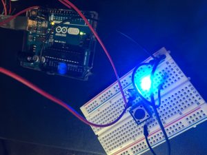
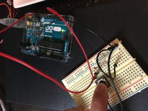
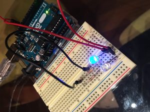
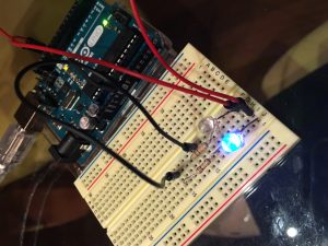
For the normal lab requirement, I had one rotating control for brightness and one rotating control for blinking rate. I mapped these controls using soldered potentiometers.

For extra credit, I  wanted to improve upon my previous piano/forte Lab 2. I mapped one pot to a variable called dynamic, which when rotated would switch from ‘p’ mode to ‘mp mode’ to ‘f’ mode. The other pot mapped to the blinking rate.

Materials

  • Jumper cables
  • Potentiometers (2)
  • Ping pong ball diffuser
  • Cotton
  • Arduino
  • 3 LED’s
  • Breadboard
  • Code (Lab Requirement)


    int sensorPin = A0;
    int sensorPin2 = A1; // select the input pin for the potentiometer
    int ledPin = 11; // select the pin for the LED
    int ledPin2 = 10;
    int ledPin3 = 9;
    int sensorValue = 0; // variable to store the value coming from the sensor
    int sensorValue2 = 0;

    void setup() {
    // declare the ledPin as an OUTPUT:
    pinMode(sensorPin, INPUT);
    pinMode(sensorPin2, INPUT);
    pinMode(ledPin, OUTPUT);
    pinMode(ledPin2, OUTPUT);
    pinMode(ledPin3, OUTPUT);
    Serial.begin(9600);
    }

    void loop() {
    // read the value from the sensor:

    sensorValue = analogRead(sensorPin);
    sensorValue2 = analogRead(sensorPin2);
    Serial.print(sensorValue);
    Serial.print(",");
    Serial.print(sensorValue2);
    Serial.println("");
    // turn the ledPin on
    analogWrite(ledPin, (sensorValue2 / 4));
    analogWrite(ledPin2, (sensorValue2 / 4));
    analogWrite(ledPin3, (sensorValue2 / 4));
    // stop the program for milliseconds:
    delay(sensorValue);
    analogWrite(ledPin, 0);
    analogWrite(ledPin2, 0);
    analogWrite(ledPin3, 0);
    // stop the program for milliseconds:
    delay(sensorValue);
    }

    Code (Extra Credit)


    // Output
    int sensorPin = A0;
    int sensorPin2 = A1; // select the input pin for the potentiometer
    int greenPin = 9; // Red LED, connected to digital pin 9
    int bluePin = 10; // Green LED, connected to digital pin 10
    int redPin = 11; // Blue LED, connected to digital pin 11
    int dynamic = 0;
    // Program variables
    int blueVal = 0; // Variables to store the values to send to the pins
    int greenVal = 0 ; // Initial values are Red full, Green and Blue off
    int redVal = 0;
    int repeat = 0;
    int i = 0; // Loop counter
    int wait = 25; // 50ms (.05 second) delay; shorten for faster fades
    //int DEBUG = 0; // DEBUG counter; if set to 1, will write values back via serial

    void setup()
    {
    pinMode(sensorPin, INPUT);
    pinMode(sensorPin2, INPUT);
    pinMode(redPin, OUTPUT); // sets the pins as output
    pinMode(greenPin, OUTPUT);
    pinMode(bluePin, OUTPUT);
    Serial.begin(9600);
    Serial.println("rotate right or left to go more p or more f");
    }

    // Main program
    void loop()
    {
    dynamic = analogRead(sensorPin);
    wait = analogRead(sensorPin2);
    if (dynamic < 300) {
    redVal = 0;
    greenVal = 0;
    blueVal = 0;

    i = 0;
    for (; i <50; i++) {
    Serial.print("dynamic ");
    Serial.print(dynamic);
    Serial.print(" wait ");
    Serial.print(wait/8);
    Serial.println();
    blueVal += 1 ;
    Serial.println(dynamic);
    analogWrite(redPin, redVal);
    analogWrite(greenPin, greenVal);
    analogWrite(bluePin, blueVal);
    delay(wait/8);
    }
    for (; i <100;i++) {
    blueVal -= 1;
    analogWrite(redPin, redVal);
    analogWrite(greenPin, greenVal);
    analogWrite(bluePin, blueVal);
    delay(wait/8);
    }

    }
    else if (dynamic < 700) {
    redVal = 0;
    greenVal = 0;
    blueVal = 0;
    i = 0;
    for (; i <50; i++) {
    redVal += 2;
    greenVal += 1;
    blueVal = 1;
    Serial.print("dynamic ");
    Serial.print(dynamic);
    Serial.print(" wait ");
    Serial.print(wait/8);
    Serial.println();
    analogWrite(redPin, redVal);
    analogWrite(greenPin, greenVal);
    analogWrite(bluePin, blueVal);
    delay(wait/8);
    }
    for (; i <100;i++) {
    greenVal -= 1;
    redVal -= 2;
    analogWrite(redPin, redVal);
    analogWrite(greenPin, greenVal);
    analogWrite(bluePin, blueVal);
    delay(wait/8);
    }

    redVal = 0;
    }
    else if (dynamic < 1050) {
    redVal = 255;
    greenVal = 0;
    blueVal = 0;
    i = 0;
    for (; i <50; i++) {
    Serial.print("dynamic ");
    Serial.print(dynamic);
    Serial.print(" wait ");
    Serial.print(wait/8);
    Serial.println();
    redVal -= 3;
    greenVal = greenVal;
    blueVal += 1;
    Serial.println(dynamic);
    analogWrite(redPin, redVal);
    analogWrite(greenPin, greenVal);
    analogWrite(bluePin, blueVal);
    delay(wait/8);
    }
    for (; i <100;i++) {
    redVal = redVal;
    greenVal += 2;
    blueVal = blueVal;
    analogWrite(redPin, redVal);
    analogWrite(greenPin, greenVal);
    analogWrite(bluePin, blueVal);
    delay(wait/8);
    }
    for (; i <150;i++) {
    redVal += 3;
    greenVal -= 1;
    blueVal -= 1;
    analogWrite(redPin, redVal);
    analogWrite(greenPin, greenVal);
    analogWrite(bluePin, blueVal);
    delay(wait/8);
    }
    redVal = 0;
    greenVal = 0;
    blueVal = 0;
    analogWrite(redPin, redVal);
    analogWrite(greenPin, greenVal);
    analogWrite(bluePin, blueVal);
    }
    else {
    }
    }

    This is what happens when dynamic is set to the highest and wait is set to almost the lowest. The color crescendo is really fast.


    RR03

    Hello! When will the prompt for RR03 be updated? It still says TBD, I believe.

    Piano and Forte

    I created a paper lantern that lights up and filters the diffused light. On occasion (as in, if positioned properly with a really low overhang), it can make a modest light pattern on my apartment ceiling.

    To interact with the lantern, people can type in music dynamic such as ‘p’, ‘pp’, ‘mp’, ‘f’, ‘ff’. For example, ‘p’ stands for piano, and a small soft blue light will fade in and fade out slowly. ‘pp’ fades in and fades out with an even softer blue light twice. ‘F’ on the other hand is loud and lively, a color crescendo. My first version’s ‘F’ fluctuated from red-green to a vibrating blue to magenta. My second iteration is more smooth in transition.

    They all fade at variable rates, representing the dynamics of their music symbolism.

    Materials

    • 1/2 Blue LED
    • 1 Button
    • Jumper cables
    • Resistors (220Ω)
    • 1 Arduino Uno
    • 1 Breadboard
    • Ping Pong Ball or Translucent Cup
    • Paper


    Code


    /*
    * Code for cross-fading 3 LEDs, red, green and blue, or one tri-color LED, using PWM
    * The program cross-fades slowly from red to green, green to blue, and blue to red
    * The debugging code assumes Arduino 0004, as it uses the new Serial.begin()-style functions
    */
    // Output
    int greenPin = 3; // Red LED, connected to digital pin 9
    int bluePin = 6; // Green LED, connected to digital pin 10
    int redPin = 11; // Blue LED, connected to digital pin 11

    // Program variables
    String dynamic;
    int blueVal = 0; // Variables to store the values to send to the pins
    int greenVal = 0 ; // Initial values are Red full, Green and Blue off
    int redVal = 0;
    int repeat= 0;
    int i = 0; // Loop counter
    int wait = 25; // 50ms (.05 second) delay; shorten for faster fades
    //int DEBUG = 0; // DEBUG counter; if set to 1, will write values back via serial

    void setup()
    {
    pinMode(redPin, OUTPUT); // sets the pins as output
    pinMode(greenPin, OUTPUT);
    pinMode(bluePin, OUTPUT);
    Serial.begin(9600);
    analogWrite(redPin, redVal);
    analogWrite(greenPin, greenVal);
    analogWrite(bluePin, blueVal);
    Serial.println("enter a music dynamic command: pp, p, mp, f, ff");

    }

    // Main program
    void loop()
    {
    i = 0;
    dynamic = "";
    while (Serial.available() == 0) {

    }
    dynamic = Serial.readString();
    if (dynamic.substring(0,1) == "p") {
    redVal = 0;
    greenVal = 0;
    blueVal = 0;
    wait = 25;
    for (repeat = 0; repeat <dynamic.length(); repeat++) {
    i = 0;
    for (; i <100; i++) {
    greenVal += (1/dynamic.length()) ;
    analogWrite(redPin, redVal);
    analogWrite(greenPin, greenVal);
    analogWrite(bluePin, blueVal);
    delay(wait);
    }
    for (; i <200;i++) {
    greenVal -= (1/dynamic.length());
    analogWrite(redPin, redVal);
    analogWrite(greenPin, greenVal);
    analogWrite(bluePin, blueVal);
    delay(wait);
    }
    }
    }
    if (dynamic == "mp") {
    redVal = 0;
    greenVal = 0;
    blueVal = 0;
    wait = 20;
    for (repeat = 0; repeat <4; repeat++) {
    i = 0;
    for (; i <100; i++) {
    redVal += 1;
    greenVal += 1;
    analogWrite(redPin, redVal);
    analogWrite(greenPin, greenVal);
    analogWrite(bluePin, blueVal);
    delay(wait);
    }
    for (; i <200;i++) {
    greenVal -= 1;
    redVal -= 1;
    analogWrite(redPin, redVal);
    analogWrite(greenPin, greenVal);
    analogWrite(bluePin, blueVal);
    delay(wait);
    }
    }
    }
    if (dynamic.substring(0,1) == "f") {
    redVal = 255;
    greenVal = 0;
    blueVal = 0;
    wait = 50;
    for (repeat = 0; repeat <dynamic.length(); repeat++) {
    i = 0;
    for (; i <100; i++) {
    redVal -= 1;
    greenVal += 1;
    blueVal =1;
    analogWrite(redPin, redVal);
    analogWrite(greenPin, greenVal);
    analogWrite(bluePin, blueVal);
    delay(wait);
    }
    for (; i <200;i++) {
    redVal = 1;
    greenVal -= 1;
    blueVal += 1;
    analogWrite(redPin, redVal);
    analogWrite(greenPin, greenVal);
    analogWrite(bluePin, blueVal);
    delay(wait);
    }
    for (; i <300;i++) {
    redVal += 1;
    greenVal =1;
    blueVal -= 1;
    analogWrite(redPin, redVal);
    analogWrite(greenPin, greenVal);
    analogWrite(bluePin, blueVal);
    delay(wait);
    }
    redVal = 0;
    greenVal = 0;
    blueVal = 0;
    analogWrite(redPin, redVal);
    analogWrite(greenPin, greenVal);
    analogWrite(bluePin, blueVal);
    }
    }
    }

    1st Iteration of ‘ff’:

    2nd Iteration of ‘ff’:

    Autodesk Fusion 360

    Autodesk Fusion 360 is the closest UI that comes to mind, bridging the tangible and the digital through 3D printing. It still shares a great deal of its UI with purely digital programs like Paint or Illustrator; users utilize the select, resize, and click interface and can quickly undo changes if they don’t like them. However, it also asks users to pretend that they are working within a 3d realm. Clicking extrude simulates the effect of building layers. Toggling effects like bevel smooth out corners into rounded edges. By inputting a radius and a click, we can stamp a hole in our work.

    After compiling the code and as we print, we can see the extension of our creativity through the hot tip of the extruder. It acts not in lieu of us, but with us, applying a mechanical hand driven by digital instructions originating from our mind. In a sense this UI both complements and goes against McCullough’s arguments. Just as industrial design fused artistic expression with technology, so do we when we 3D print. However at the same time, his argument—that software currently is merely the labor of our minds—is not disproven by Autodesk Fusion 360.

    If I could redesign aspects of the software and if I had the technical/scientific chops, I would consider adding a holographic projection portion to the software. This way, instead of dragging the mouse around to “camera/zoom” view my model, I would be able to circle around it and observe it as if it were physical. Perhaps, the software could be improved by functional phicons, like a knife that could digitally slice the model. This knife would be analogous to the ActiveLens from metaDesk that emulated a jeweler’s magnifying glass.

    The last thing I attempted to make on Autodesk Fusion 360-Stitch from Lilo & Stitch. Obviously I wasn’t getting too far, haha.

    Button || <3 in Binary

    Description


    In my first attempt, I created a circuit that causes the LED to blink in response to a button. When the button is pressed, the current is redirected away from the LED back to GND. Otherwise, the current flows through the LED.

    In a second attempt, I created a created a parallel circuit where the blinks of the two LED’s symbolize the binary language running our world. One LED is a 0 and the other LED is a 1. Together, they blink 0011110000110011, which represents ‘<3’ in ASCII. Between each looped sequence is a 2 second pause.

    Both examples symbolize a theme of the course–transducing what is digital into something more human-friendly and intuitive.


    Components


    • 1/2 Blue LED
    • 1 Button
    • Jumper cables
    • Resistors (220Ω)
    • 1 Arduino Uno
    • 1 Breadboard

    Code


    Button Code

    int buttonInput = 2;
    int LED = 13;
    int buttonState = 0;
    
    void setup() {
     pinMode(LED, OUTPUT);
     pinMode(buttonInput, INPUT);
     buttonState = LOW;
    
    }
    
    void loop() {
     buttonState = digitalRead(buttonInput);
     //When button is pressed, LED turns off
     if (buttonState == HIGH) {
     digitalWrite(LED, LOW);
     } else {
     digitalWrite(LED, HIGH);
     }
    }

    Binary Code

    const int led1 = 13;
    const int led2 = 12;
    const int buttonInput = 2;
    
    int buttonPress = 0;
    int buttonCurrent = 0;
    int buttonOld = 0;
     
    void setup() {
     pinMode(led1, OUTPUT);
     pinMode(led2, OUTPUT);
    
     
    }
    
    void LEDfunc(int ledPin, int repeat) {
     for (repeat; repeat>0; repeat--) {
     digitalWrite(ledPin, HIGH);
     delay(200);
     digitalWrite(ledPin, LOW);
     delay(200);
     }
    }
    void loop() {
     delay(2000);
     LEDfunc(led1, 2);
     LEDfunc(led2,4);
     LEDfunc(led1, 4);
     LEDfunc(led2, 2);
     LEDfunc(led1, 2);
     LEDfunc(led2,2);
    
    }


    Button Version

    When button is not depressed IMG_0338

    Binary Version

    IMG_0374 IMG_0377

    Photoshop

    Ever since I was little, Photoshop has always been my personal digital playground. In its UI, I pushed around pixels into avatars, banners, and layouts to cultivate an online identity in forums. In doing so, I began to engage in a form of social computing, even though everything I made was intangible. I would creatively manipulate photos into collages, completing actions every time I made something. After awhile, all the commands of the interface, whether it be Ctrl + T or selective coloring, became instinctive operations.

    When I interacted with its UI, I noticed that much of it pulled from reality. Many tools were named after tools: brush, lasso, pencil, etc. The software carries effects that imitate watercolors, graphite strokes, and mosaics. Photoshop referred to the tangible world for a better user experience much like how early computers utilized symbols like files and trashcans. Even the documents are called canvases, as if to reaffirm that even though the work is behind a screen, it is still a piece of art.

    My mother and aunt, as graphic designers, were the first ones to introduce design to me, and perhaps the personal connection is also why I love the software. I learned it through not only solo experimentation but also by studying their working process. In that sense, my education began in an interpsychological manner; I would create characters from circles and squares under their guidance until I was adept enough to study tutorials and learn intrapsychologically.