Description:
I used the example code (_3_LED_Fading.txt and Serial_LED.txt) for this lab. The fading code faded one LED color in and out and into the next, forming the effect of new colors like purple and green.
Once that was tested and completed, I adjusted the serial LED code to accept user inputs via the Serial Monitor to adjust the brightness of each LED. Each r, g or b in the Serial Monitor now represents 10% of the possible brightness (255) of each LED. For example rrr = (3/10*255). As a diffuser, I used an old small milk bottle and stuffed it with 2 coffee filters to diffuse the light from the LEDs. The effect was pretty rad.
Components:
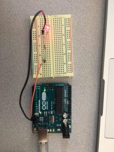
- 1 Arduino
- 1 Breadboard
- 3 LEDs (b,r,g)
- 3 Resistors (220 ohms)
- 4 connecting wires
- 1 USB cable
- 1 Laptop
- 1 Milk bottle
- 2 Coffee filters
Code:
_3_LED_Fading
// Output
int redPin = 9; // Red LED, connected to digital pin 9
int greenPin = 10; // Green LED, connected to digital pin 10
int bluePin = 11; // Blue LED, connected to digital pin 11
// Program variables
int redVal = 255; // Variables to store the values to send to the pins
int greenVal = 1; // Initial values are Red full, Green and Blue off
int blueVal = 1;
int i = 0; // Loop counter
int wait = 18; // 50ms (.05 second) delay; shorten for faster fades
int DEBUG = 0; // DEBUG counter; if set to 1, will write values back via serial
void setup()
{
pinMode(redPin, OUTPUT); // sets the pins as output
pinMode(greenPin, OUTPUT);
pinMode(bluePin, OUTPUT);
if (DEBUG) { // If we want to see the pin values for debugging…
Serial.begin(9600); // …set up the serial ouput on 0004 style
}
}
// Main program
void loop()
{
i += 1; // Increment counter
if (i < 255) // First phase of fades
{
redVal -= 1; // Red down
greenVal += 1; // Green up
blueVal = 1; // Blue low
}
else if (i < 509) // Second phase of fades
{
redVal = 1; // Red low
greenVal -= 1; // Green down
blueVal += 1; // Blue up
}
else if (i < 763) // Third phase of fades
{
redVal += 1; // Red up
greenVal = 1; // Green low
blueVal -= 1; // Blue down
}
else // Re-set the counter, and start the fades again
{
i = 1;
}
analogWrite(redPin, redVal); // Write current values to LED pins
analogWrite(greenPin, greenVal);
analogWrite(bluePin, blueVal);
if (DEBUG) { // If we want to read the output
DEBUG += 1; // Increment the DEBUG counter
if (DEBUG > 10) // Print every 10 loops
{
DEBUG = 1; // Reset the counter
Serial.print(i); // Serial commands in 0004 style
Serial.print(“t”); // Print a tab
Serial.print(“R:”); // Indicate that output is red value
Serial.print(redVal); // Print red value
Serial.print(“t”); // Print a tab
Serial.print(“G:”); // Repeat for green and blue…
Serial.print(greenVal);
Serial.print(“t”);
Serial.print(“B:”);
Serial.println(blueVal); // println, to end with a carriage return
}
}
delay(wait); // Pause for ‘wait’ milliseconds before resuming the loop
}
Serial_LED
char serInString[100]; // array that will hold the different bytes of the string. 100=100characters;
// -> you must state how long the array will be else it won’t work properly
char colorCode;
float colorVal;
int redPin = 11; // Red LED, connected to digital pin 9
int greenPin = 9; // Green LED, connected to digital pin 10
int bluePin = 10; // Blue LED, connected to digital pin 11
void setup() {
pinMode(redPin, OUTPUT); // sets the pins as output
pinMode(greenPin, OUTPUT);
pinMode(bluePin, OUTPUT);
Serial.begin(9600);
analogWrite(redPin, 80); // set them all to mid brightness
analogWrite(greenPin, 80); // set them all to mid brightness
analogWrite(bluePin, 80); // set them all to mid brightness
}
void loop () {
// clear the string
memset(serInString, 0, 100);
//read the serial port and create a string out of what you read
readSerialString(serInString);
colorCode = serInString[0];
if( colorCode == ‘r’ || colorCode == ‘g’ || colorCode == ‘b’ ) {
colorVal = strlen(serInString);
colorVal = (colorVal/10*255); // the number of times you type r, g or b defines the brightness (% of)
if (colorVal>255)
{ // need a way to turn off our colors
colorVal = 0;}
Serial.print(“setting color “);
Serial.print(colorCode);
Serial.print(” to “);
Serial.print(colorVal);
Serial.println();
serInString[0] = 0; // indicates we’ve used this string
if(colorCode == ‘r’)
analogWrite(redPin, colorVal);
else if(colorCode == ‘g’)
analogWrite(greenPin, colorVal);
else if(colorCode == ‘b’)
analogWrite(bluePin, colorVal);
}
delay(100); // wait a bit, for serial data
}
//read a string from the serial and store it in an array
//you must supply the array variable
void readSerialString (char *strArray) {
int i = 0;
if(!Serial.available()) {
return;
}
while (Serial.available()) {
strArray[i] = Serial.read();
i++;
}
}