Introduction
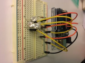
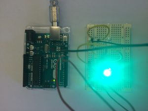
For this project, I got very interested in creating a paper origami lamp as the diffuser, and got interested in how to create a mixed color of purple, orange, yellow out of the R, G, B LED lights we have in our kit.
I compared a series of paper origami lamps online and tried one which turned out to be too long in scale for our mini LED lights. So the one I used in this project is my second attempt, which matches the scale of the LED lights, yay! :p
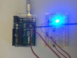
For the color mixing part, I used Adobe Illustrator to figure out the basic RGB values for color mixing patterns for purple, orange and yellow, and it turned out to be quite interesting. So for purple, in my code, I use equal brightness of red light and blue light and turn the brightness of green light to 0; for yellow, it’s similarly mixed via equal brightness of red and green; while for orange, it requires the green light to have half or even lower brightness when compared to the red light.
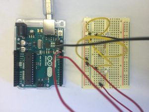
Components
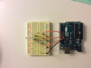
- 1x Arduino Uno
- 1x Breadboard
- 3x Jumper Wires
- 3x LEDs (R/G/B)
- 3x 220Ω Resistors
- 1x USB Cable
- 1x Macbook Pro
- 1x Paper
- 1x Double-Sided Tape
Code
/* Safei modified version
* Serial RGB LED
* —————
* Serial commands control the brightness of R,G,B LEDs
*
* Command structure is “<colorCode><colorVal>”, where “colorCode” is
* one of “r”,”g”,or “b” and “colorVal” is a number 0 to 255.
* E.g. “r0” turns the red LED off.
* “g127” turns the green LED to half brightness
* “b64” turns the blue LED to 1/4 brightness
*
* Created 18 October 2006
* copyleft 2006 Tod E. Kurt <tod@todbot.com
* http://todbot.com/
*/
char serInString[100]; // array that will hold the different bytes of the string. 100=100characters;
// ->you must state how long the array will be else it won’t work properly
char colorCode;
int colorVal;
int colorVal2;
int redPin = 9; // Red LED, connected to digital pin 9
int greenPin = 10; // Green LED, connected to digital pin 10
int bluePin = 11; // Blue LED, connected to digital pin 11
void setup() {
pinMode(redPin, OUTPUT); // sets the pins as output
pinMode(greenPin, OUTPUT);
pinMode(bluePin, OUTPUT);
Serial.begin(9600);
analogWrite(redPin, 0); // set them all to mid brightness
analogWrite(greenPin, 0); // set them all to mid brightness
analogWrite(bluePin, 0); // set them all to mid brightness
Serial.println(“enter color command (e.g. you can press up to 10 times of the initial letter of 6 different colors – r, g, b, o (for orange), p (for purple), y (for yellow), the brightness of the color will increase 20% by one letter input) :”);
}
void loop () {
// clear the string
memset(serInString, 0, 100);
//read the serial port and create a string out of what you read
readSerialString(serInString);
colorCode = serInString[0];
if( colorCode == ‘r’ || colorCode == ‘g’ || colorCode == ‘b’ || colorCode == ‘o’ || colorCode == ‘p’ || colorCode == ‘y’ ) {
//colorVal = atoi(serInString+1);
colorVal = 0;
for (int i=0; i<strlen(serInString); i++) {
if( colorCode == ‘r’ || colorCode == ‘g’ || colorCode == ‘b’ || colorCode == ‘o’ || colorCode == ‘p’ || colorCode == ‘y’ )
{
colorVal += 1;
}
}
if (strlen(serInString) > 10){
colorVal = 0;
}
//colorVal = strlen(serInString);
colorVal = colorVal*25.5;
colorVal2 = colorVal/2;
Serial.print(“setting color “);
Serial.print(colorCode);
Serial.print(” to “);
Serial.print(colorVal);
Serial.println();
serInString[0] = 0; // indicates we’ve used this string
if(colorCode == ‘r’) {
analogWrite(redPin, colorVal);
analogWrite(greenPin, 0);
analogWrite(bluePin, 0);}
else if(colorCode == ‘g’) {
analogWrite(greenPin, colorVal);
analogWrite(bluePin, 0);
analogWrite(redPin, 0);}
else if(colorCode == ‘b’) {
analogWrite(bluePin, colorVal);
analogWrite(greenPin, 0);
analogWrite(redPin, 0);}
else if(colorCode == ‘o’) {
analogWrite(redPin, colorVal);
analogWrite(greenPin, colorVal2);
analogWrite(bluePin, 0);}
else if(colorCode == ‘y’) {
analogWrite(redPin, colorVal);
analogWrite(greenPin, colorVal);
analogWrite(bluePin, 0);}
else if(colorCode == ‘p’) {
analogWrite(redPin, colorVal);
analogWrite(bluePin, colorVal);
analogWrite(greenPin, 0);}
}
delay(100); // wait a bit, for serial data
}
//read a string from the serial and store it in an array
//you must supply the array variable
void readSerialString (char *strArray) {
int i = 0;
if(!Serial.available()) {
return;
}
while (Serial.available()) {
strArray[i] = Serial.read();
i++;
}
}
Photos + Video
https://youtu.be/8syuyGd4WX8