Description
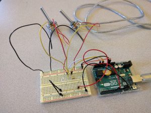
This circuit uses two potentiometers, one to control the brightness of the LED and the other to control the blinking rate. Within each blink, the brightness is held constant. All measurements are done using analog inputs on the Arduino.
Components
- Arduino
- 1 LED
- 1 Resistor (220Ω)
- 7 Wires
- 1 Breadboard
- 2 Potentiometers
Code
int rateSensorPin = A0;    // select the input pin for the rate potentiometer

int brightSensorPin = A2;  // select the input pin for the brightness potentiometer

int ledPin = 9;      // select the pin for the LED

int rateValue = 0;  // variable to store rate pot value

int brightValue = 0;  // variable to store brightness pot value

void setup() {

  // declare the ledPin as an OUTPUT:

  pinMode(ledPin, OUTPUT);

}
void loop() {
// read the value from the sensors:
rateValue = analogRead(rateSensorPin);
brightValue = analogRead(brightSensorPin);
// turn the ledPin on, convert from 0-1023 scale to 0-255
analogWrite(ledPin, brightValue/4);
// stop the program for
delay(rateValue);
// turn the ledPin off:
digitalWrite(ledPin, LOW);
// stop the program for for
delay(rateValue);
}