Description
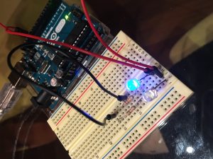
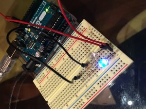
In my first attempt, I created a circuit that causes the LED to blink in response to a button. When the button is pressed, the current is redirected away from the LED back to GND. Otherwise, the current flows through the LED.
In a second attempt, I created a created a parallel circuit where the blinks of the two LED’s symbolize the binary language running our world. One LED is a 0 and the other LED is a 1. Together, they blink 0011110000110011, which represents ‘<3’ in ASCII. Between each looped sequence is a 2 second pause.
Both examples symbolize a theme of the course–transducing what is digital into something more human-friendly and intuitive.
Components
- 1/2 Blue LED
- 1 Button
- Jumper cables
- Resistors (220Ω)
- 1 Arduino Uno
- 1 Breadboard
Code
Button Code
int buttonInput = 2;
int LED = 13;
int buttonState = 0;

void setup() {
 pinMode(LED, OUTPUT);
 pinMode(buttonInput, INPUT);
 buttonState = LOW;

}

void loop() {
 buttonState = digitalRead(buttonInput);
 //When button is pressed, LED turns off
 if (buttonState == HIGH) {
 digitalWrite(LED, LOW);
 } else {
 digitalWrite(LED, HIGH);
 }
}
Binary Code
const int led1 = 13;
const int led2 = 12;
const int buttonInput = 2;

int buttonPress = 0;
int buttonCurrent = 0;
int buttonOld = 0;

void setup() {
 pinMode(led1, OUTPUT);
 pinMode(led2, OUTPUT);


}

void LEDfunc(int ledPin, int repeat) {
 for (repeat; repeat>0; repeat--) {
 digitalWrite(ledPin, HIGH);
 delay(200);
 digitalWrite(ledPin, LOW);
 delay(200);
 }
}
void loop() {
 delay(2000);
 LEDfunc(led1, 2);
 LEDfunc(led2,4);
 LEDfunc(led1, 4);
 LEDfunc(led2, 2);
 LEDfunc(led1, 2);
 LEDfunc(led2,2);

}
Button Version
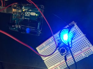
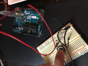
Binary Version