In our status update, we’ll provide a reminder of where we started, we’ll cover our new name, where we are with prototyping, and show you what’s been inspiring us.

In our status update, we’ll provide a reminder of where we started, we’ll cover our new name, where we are with prototyping, and show you what’s been inspiring us.
We plan to continue the project we outlined in our midterm presentation. The patch will work with Adafruit FLORA’s suite of wearable, sewable products in order to get a close-to-skin form factor. For a prototype, this will likely involve fabric rather than something that adheres to the skin, but should be wearable nonetheless.
Here is the list of products we anticipate experimenting with:
While we do not anticipate using each item to create our prototype, we see this as an opportunity to try out different sensations and sensors to see what people respond to the most, and use those for our prototype.
Description:
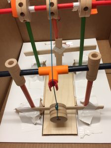
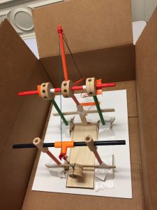
Our group wanted to attempt an unconventional cuckoo clock, counter to the example we saw in class with the 4-bar joint. Instead of a cuckoo that emerged horizontally from the door, we designed a cuckoo that plunged through a trapdoor instead. The primary mechanism used to move the trapdoor and lower the cuckoo through the opening is a pulley system. As the pulley is pulled in one direction, the trapdoor moves out of the way to reveal an exit. As the pulley is pulled and the trapdoor is moved back, the cuckoo also lowers. The cuckoo is mitigated from falling outside the bounds of the trapdoor exit until the opening is wide enough for it to plunge through. The cuckoo can then continue to be lowered, or reigned back into the clock by pulling the pulley in the opposite direction. The trapdoor is prevented from collapsing on the cuckoo prematurely by means of (1) the distances used in both the strings affixed to the door and the cuckoo, and (2) the rotational distance between the door and the peg that pushes it back into place.
To hold the system in place and direct accurate movement, we have in place four poles around the trapdoor’s perimeter (but not affixed to the trapdoor). These poles are taped securely to the surface of the foam board/clock base. While there are three gears in our structure, only the center one is unrestrained by a foundational support component. For our design, it is imperative that thread lines are measured to have sufficient tension and slack when appropriate. Otherwise, the system will fail. If the support structure also shifts (whether at foundation or at suspension), the system is likely to fail due to the shifting of the trapdoor in and out of place. Also necessary is a wall to prevent the cuckoo from traveling with the trapdoor as it slides back, as opposed to falling through the exit.
We think this cuckoo clock mechanism design is appropriate, considering the majority of cuckoo clocks hang on the wall, and so have room beneath them that can be utilized.
Components Used:
The HTC Vive experience was significantly more impressive than I had expected. Having tried out an early version of the Oculus Rift, I was expecting incremental improvements over that system, rather than the enormous gains made by the Vive, especially in terms of interactivity and realism. It passed the “bat-twitch” test for me, as Wired called it. For instance, in the whale encounter, I was a bit worried what was going to happen when it flapped its tail, and I think I flinched quite a bit. Although my favorite part was the TiltBrush, and being able to draw with any number of tools and really move around within my creation. It feels like such a boon for creativity, to be able to create something and see it immediately (like the best parts of coding, being able to test whether your code works immediately, and see results), vs. say, painting with oils or photography with film.
I think the areas for enhancement are tied to the areas I found lacking: namely, having a sense for where I was in space, and wanting to stop worrying about crashing into something or tripping over the cable near my feet. Those worries kept me from being physically free in a way that would translate to the VR experience. I also think it could be improved by making it more social. It was fun to have people’s voices present from the room in my experience, and to have reassurance that I wasn’t going to hurt myself, but I haven’t yet tried any VR experiences that allow for multiple people, and I think that would really enhance the experience. Those seem to already exist, based on the Wired article, so it would be neat to get to try them. I think improvements in processing and battery power will soon be able to address some of the issues with physicality and cables and tethering.
One additional thing that I do worry about, but didn’t while having the experience:
“One of the underappreciated aspects of synthetic reality is that every virtual world is potentially a total surveillance state. By definition, everything inside a VR or MR world is tracked. After all, the more precisely and comprehensively your body and your behavior are tracked, the better your experience will be.”
As someone at the I School, I feel it’s important for us to pay attention to the issue of privacy and surveillance, as well. Do these teams have privacy practitioners on them? Should we be creating a framework here, or at least be thinking about one?
Description:
For this lab, I wanted to test how much power our little DC motors have. Since it’s acknowledged that they don’t have much torque, I didn’t want to choose something too heavy, but I did want to extend the range of the spinning motion so that it would be visible from far away. Looking around my apartment, I happened to have a poster tube sitting around, which I realized would make the perfect object: it’s long but slender, doesn’t weigh much but it stable, and is round, so I could fairly easily spin it with the motor without getting too much vibration.
So, I created a monochrome version of a barber’s pole:
First, I used the potentiometer as the speed control so that I could “lock in” a spin speed:
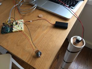
But after that, I wanted to try out using the FSR so that I could control the spin while holding the motor, so that I’d have I/O coincidence. That’s what I’ll be demonstrating in class.
One interesting observation I had was that with a heavy-ish weight, the motor takes quite a bit of “revving” to get to a level of power sufficient to overcome the inertia. And then, after removing power, my barber pole keeps spinning for quite some time. Interesting to watch it in action.
Components:
Code:
(This is the final code, using the FSR rather than the potentiometer.)
int potPin = 0; // select the input pin for the potentiometer/FSR

int motorPin = 9; // select the pin for the Motor

int val = 0; // variable to store the value coming from the sensor

void setup() {

Serial.begin(9600);

}

void loop() {

val = analogRead(potPin); // read the value from the sensor, between 0 - 1023

val = map(val, 0, 1023, 0, 255);

Serial.println(val);

analogWrite(motorPin, val); // analogWrite can be between 0-255

}
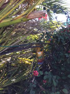
It’s interesting to notice some of the design interventions that have already been applied around campus to deter the very thoughtless acts that I was looking for. For one, all of the trash cans I’ve noticed have a peaked or domed design, such that pieces of trash do not balance on top of the trash can. I imagine this is so that people will actually put their trash INSIDE the trash can rather than on top of it. However, that doesn’t quite stop people from leaving trash wherever they can find a supporting base for it:

Including in a tree!
One of the things I do regularly is wrap my teabag string around the handle of my mug:

I hadn’t thought of this as a thoughtless act until seeing it in one of the Pinterest streams. But it accomplishes my goal of not having the teabag become lost inside the mug when I pour hot water over it. Baristas tend to do the same thing: if they put a teabag in your commuter mug, they’ll screw the lid on with the teabag label hanging out. One potential design update is to give commuter mugs a small notch where the teabag string can be held securely. However, a potentially better one is just to have a tea strainer inside the mug, which some designs already accomplish. That works well for both loose-leaf tea and bagged tea.
While shopping for groceries last night (and TJ’s was as crowded as I’ve ever seen it—it was right before the debate, and Sunday night, and everybody and their mother wanted to get groceries for the week. Suffice it to say, I was waiting for a while with a rather heavy basket. So I placed it on the floor, and pushed it along with my foot when the line would move forward.

I see this also in airport lines, when people push their heavy luggage along the floor rather than picking it up and carrying it forward as the line moves along. A design improvement could be a place for people to keep handbaskets or small but heavy items up at waist level as they wait in line, for instance with a bar-height shelf. It would also serve to keep the line orderly.
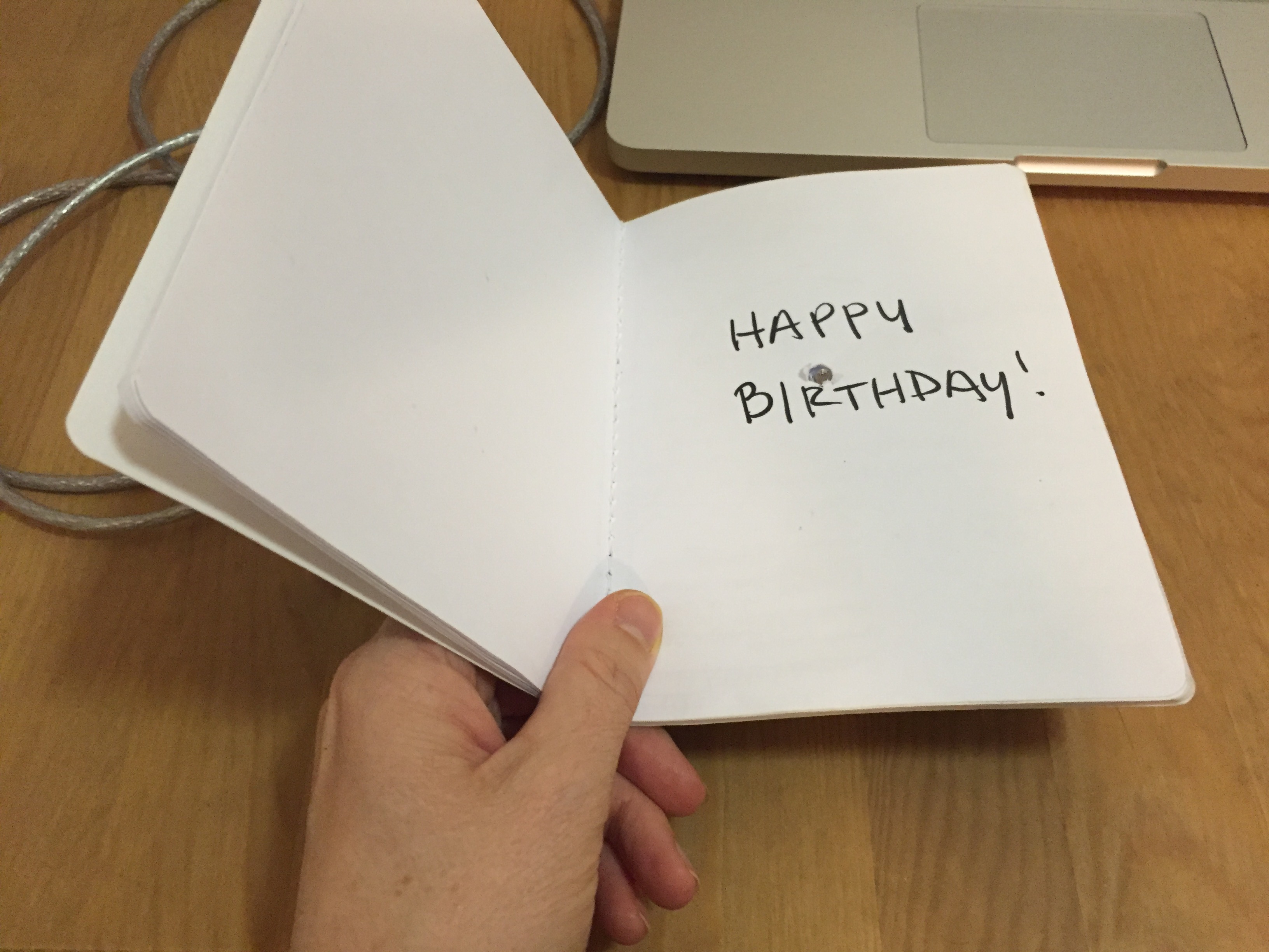
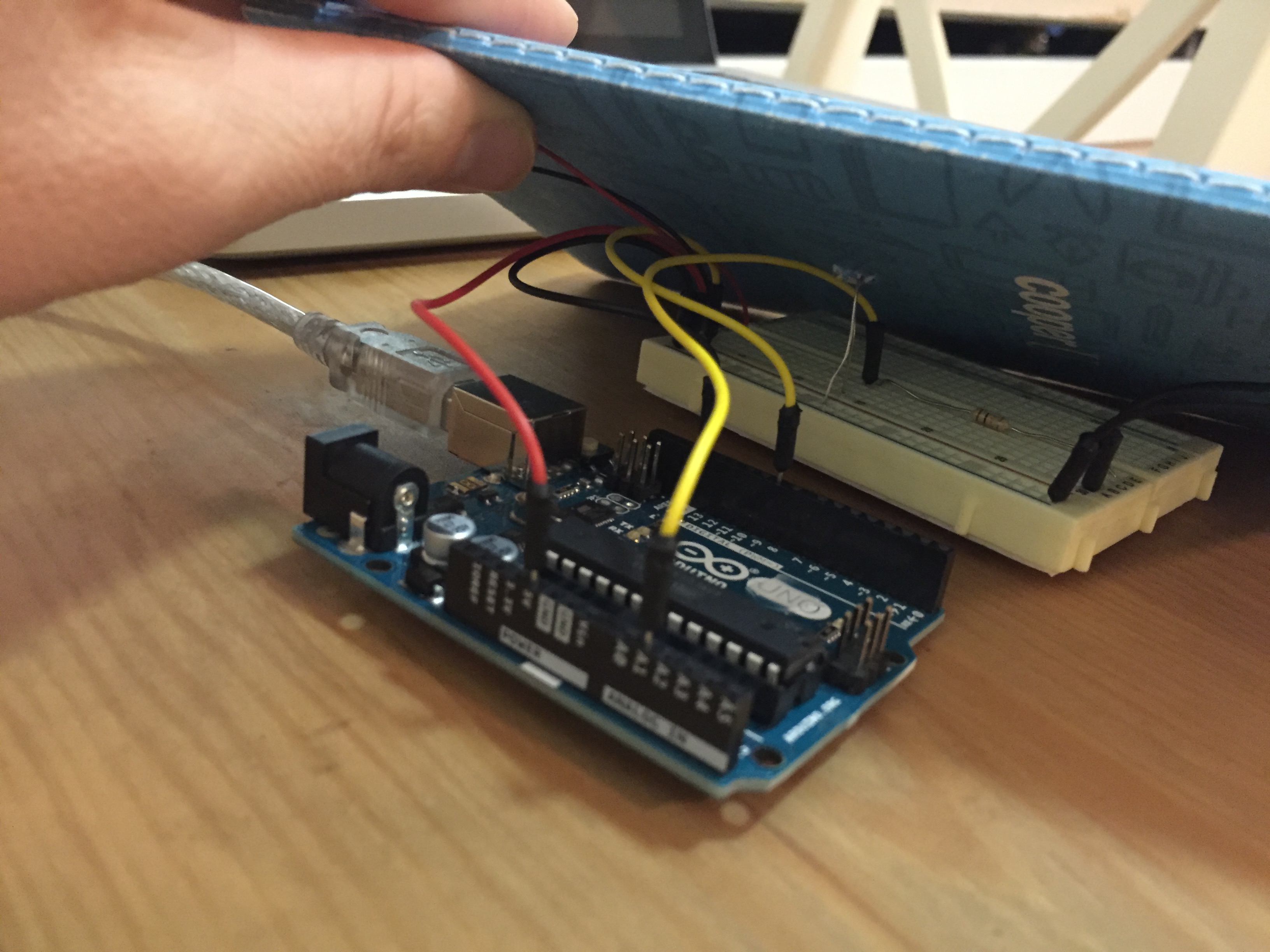
Description:
For this lab, I decided to make the best birthday card ever. For those who just can’t get enough of having people sing them Happy Birthday (or those who like to celebrate for an entire month—long after their friends have grown tired of singing Happy Birthday to them), this birthday card is for them. Every time the special birthday lady or gentleman opens the card, it plays them Happy Birthday. It uses a photocell to determine when the card is opened, and I used a modified notebook to stand in for the card because I don’t actually have any birthday cards lying around, sadly. Thankfully for those in the same room, the card will stop playing the melody, but will start again from the beginning once opened again.
Components:
Code:
// TUI Lab 05 - Molly

// Happy birthday melody sourced from http://forum.arduino.cc/index.php?topic=178460.0
int speakerPin = 9;
int photoPin = A1;
int length = 28; // the number of notes
char notes[] = "GGAGcB GGAGdc GGxecBA yyecdc";
int beats[] = { 2, 2, 8, 8, 8, 16, 1, 2, 2, 8, 8,8, 16, 1, 2,2,8,8,8,8,16, 1,2,2,8,8,8,16 };
int tempo = 150;
int val = 0;
void playTone(int tone, int duration) {
for (long i = 0; i < duration * 1000L; i += tone * 2) {
digitalWrite(speakerPin, HIGH);
delayMicroseconds(tone);
digitalWrite(speakerPin, LOW);
delayMicroseconds(tone);
}
}
void playNote(char note, int duration) {
char names[] = {'C', 'D', 'E', 'F', 'G', 'A', 'B',
'c', 'd', 'e', 'f', 'g', 'a', 'b',
'x', 'y' };
int tones[] = { 1915, 1700, 1519, 1432, 1275, 1136, 1014,
956, 834, 765, 593, 468, 346, 224,
655 , 715 };
int SPEE = 5;
// play the tone corresponding to the note name
for (int i = 0; i < 17; i++) {
if (names[i] == note) {
int newduration = duration/SPEE;
playTone(tones[i], newduration);
}
}
}
void setup() {
pinMode(speakerPin, OUTPUT);
Serial.begin(9600);
}
void loop() {
Serial.print("Value:");
Serial.print(analogRead(photoPin));
while (analogRead(photoPin) > 200) {
for (int i = 0; i < length; i++) {
if (notes[i] == ' ' and analogRead(photoPin) < 200) {
delay(beats[i] * tempo); // rest
}
else if (analogRead(photoPin) < 200) {
playNote(notes[i], beats[i] * tempo);
}
else break;
// pause between notes
delay(tempo);
}
}
}
We are proposing a patch that you wear on your skin. The patch can generate warmth, light (possibly in shapes), and pressure. The receiver can then send these sensations back to the original sender. See sketches below for examples.
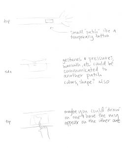
Small patch, worn on the arm (similar to a temporary tattoo). Allows for sharing gestures, like a stroke of the arm, or sharing a drawing that you feel and that appears on your patch.

Pre-determined shapes (ex: happy face) could be shared when experiencing certain emotions. Can also share a feeling or warmth of a ‘hug’ via a pressurized warmth.
One of the objects that most surprised and delighted me was the program guide to an architectural/industrial design exhibition for Heatherwick Studio at the LA County Museum of Art a few years back. Normally, one goes to a museum or gallery show and grabs a program to hold while walking through the exhibit, only to return it to the docent at the end or toss it carelessly into the trash after returning home. As Blauvelt would call it, this is the “ritual of use.” The guides may reference artworks, may even include reproductions of the art on the walls, but they are just that—reproductions—that no one would confuse with the real thing (no cargo cult there, no one would be duped). A program guide is merely a functional artifact that assists a visitor in identifying and understanding the works of art, which appear on the walls or within the gallery.
But not from this show. When I returned home, I hung the gallery guide on my wall.
Of course, it wasn’t “art” per se, but the experience of obtaining the gallery guide lent it enough emotional heft that I held onto the guide, rolled it like a small poster and cushioned it in my purse on the way home, and later mounted it on my wall. It even traveled with me when I moved from LA to Berkeley.
A printed guide for an art show is an entirely everyday object, so why all the fuss? To begin with, obtaining the gallery guide required work. There was an industrial-sized dispenser, with rolls and rolls of uncut paper guides, which had to be unrolled by hand, with the help of the room-sized dispenser. The docent merely watched as visitors unrolled and trimmed their own guides:
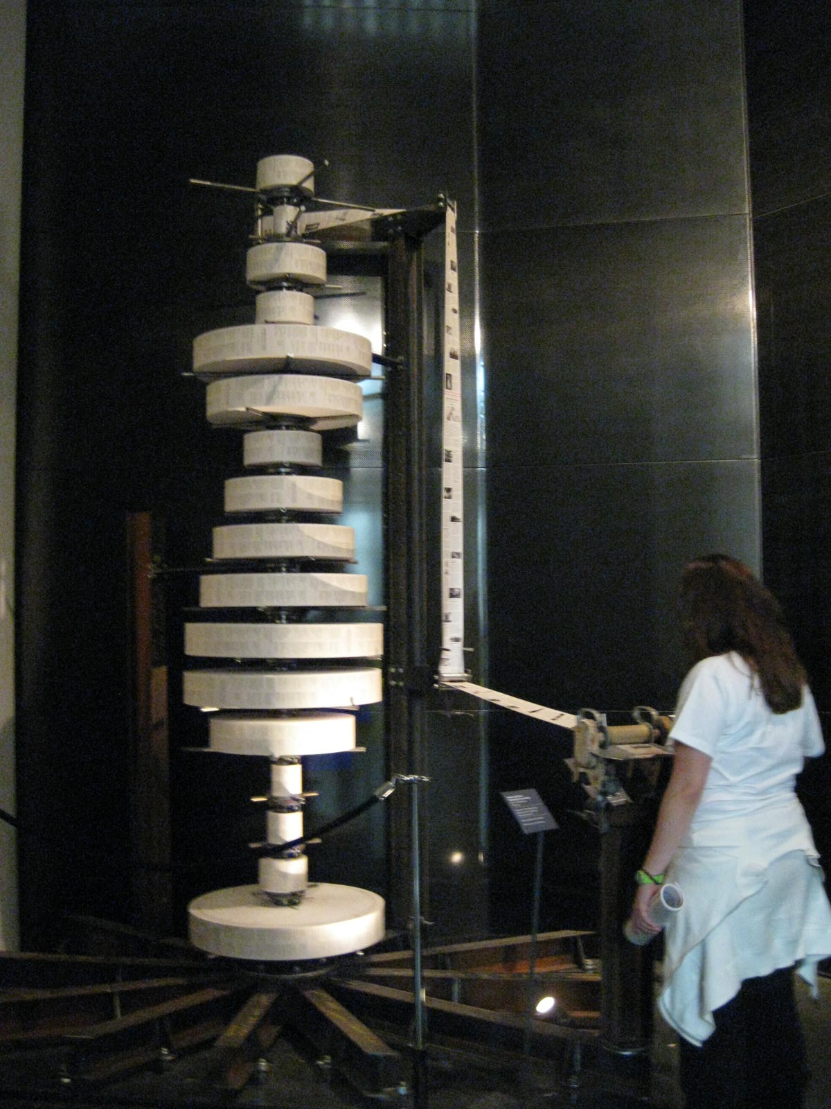
(photo from http://www.carolinebanks.co.uk/wp-content/uploads/Thomas-Heatherwick-VA-4.jpg)
At the end of that process, you had your own personal gallery guide. It felt like it was meant entirely for you, because you had had ownership in the creation of that single artifact. On the front side of the guide was a summary of the works present in the exhibition. On the back side, a repeating graphic design of the inciting questions that led the studio to create the various works of art/design present in the exhibition. Thus, the guide included both the genesis and output, two ends of the spectrum. It elucidated all parts of the process. In this sense, it gave more meaning to each of the artifacts present in the show; I, as a visitor, had a small sense of ownership over each artifact, because I had an insight into the mental model of the creator. The questions were provocative, but they dealt with aspects of the everyday. Can mistakes in aluminum extrusion create public seating? Can a chair be made completely symmetrical? And so on. This gallery guide, while technically only a long piece of cardstock paper, completely overturned my conception of the limits of program guides and the opportunities for creativity in even the most mundane and quotidian items. Instead of becoming a piece of trash, the guide became a portable reminder of the exhibition, an artistic decoration, and a multifunctional piece of paper—both referential and provocative.
* The entire show was fabulous and I recommend you check out Heatherwick Studio’s work, especially two versions of seating: the Extrusion series and the Spun chairs. Two vastly different takes on public seating. Both are beautiful, functional, and amazing, and the studio has work ranging in scale from a handbag to a city park.
Description:
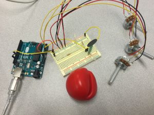
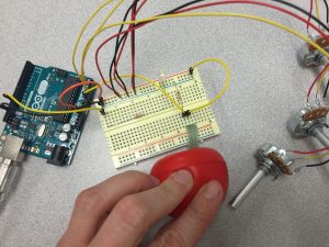
For this lab, I wanted to focus on transferring data from multiple variables and multiple sensors from Arduino into Processing. I was less concerned with what visualization to make than how to give someone more control over it and how to allow it to have multiple input streams. Because the photocell was too sensitive for easy daylight use, I stuck with the FSR for my main sensor. I kept the LED within the circuit so that it could provide me with a backup indication of the pressure on my sensor, and then I added three pots back into the circuit. Each pot controls RGB values, and can be adjusted independently. The FSR I covered with a stress-reliever type foam ball with a slit cut into it. This allowed me to slip it over the FSR and it could act as a diffuser for the squeeze pressure on the ball. This way I can squeeze on the ball in general and still affect the FSR value. The visualization responds quickly to changes in pressure and color. (The nice thing about using RGB values instead of RGB LEDs is that we can actually get additive white onscreen!)
I also ran into some problems in the making of this visualization: Processing was not correctly reading in the final value from the serial input. After troubleshooting to determine that the problem was indeed within Processing, I added in a dummy value as a final value in my Arduino output as a quick solution. I also had an issue where I was getting a “USB device drawing too much power” from my computer. After trying a few solutions, I realized that two of my pots had shifted on the desk and were touching bare wire at one spot. After rearranging and separating them, I was able to get the circuit working again.
Here is a GIF of my animation (I am squeezing with one hand and adjusting the pots with the other hand):

And my circuit:
Components:
– Arduino Uno
– breadboard
– 1 LED
– 1 220 ohm resistor
– 1 FSR
– 1 10 ohm resistor
– 3 potentiometers
– jumper wires
Arduino Code:
/*

 Lab04 - Sensing: Photocells and FSR

 Molly Mahar
*/
int FSRcellReading = 0; // initialize value read from the FSR
int ledPin = 11;
int LEDbrightness = 0;
int rPot = A1;
int rVal = 0;
int gPot = A2;
int gVal = 0;
int bPot = A3;
int bVal = 0;
void setup() {
// initialize serial communications at 9600 bps:
Serial.begin(9600);
// declare the led pin(s) as output:
pinMode(ledPin, OUTPUT);
}
void loop() {
// this will map the LED brightness according to the pressure placed on the FSR:
FSRcellReading = analogRead(A0);
//now we have to map 0-1023 to 0-255 since thats the range analogWrite uses.
LEDbrightness = map(FSRcellReading, 0, 1023, 0, 255);
// Also want to read in the values from the three pots, and map those to 0-255 RGB values:
rVal = map(analogRead(rPot), 0, 1023, 0, 255);
gVal = map(analogRead(gPot), 0, 1023, 0, 255);
bVal = map(analogRead(bPot), 0, 1023, 0, 255);
analogWrite(ledPin, LEDbrightness); // PWM the LED with the pot value (divided by 4 to fit in a byte)
//construct a message to Processing with multiple values in arduino
//we can't just send a string from here since it only officially understands 'bytes'
// Got help in this instance from this post: https://processing.org/discourse/beta/num_1193069410.html
Serial.print(FSRcellReading);
Serial.print(",");
Serial.print(rVal);
Serial.print(",");
Serial.print(gVal);
Serial.print(",");
Serial.print(bVal);
Serial.print(",");
// Not sure why I'm having this problem, but Processing was somehow not reading the last value?
// I checked in the serial monitor and it was getting sent from Arduino
// So I'm adding a final value into the serial printout, so that all my rgb values will be read in Processing
Serial.print(0,DEC);
Serial.print("|");
//Serial.println([FSRcellReading, rVal, gVal, bVal]);
delay(100); // pause at that level before looping through again
}
Processing Code:
/* PROCESSING SKETCH

 * Based on the original ball code by Noura Howell

 * Modified for Lab 4 by Molly Mahar

 */

import processing.serial.*;

String portname = "/dev/cu.usbmodem1421"; // or "COM5"

Serial port;

String buf="";

int cr = 13; // ASCII return == 13

int lf = 10; // ASCII linefeed == 10

//int serialVal = 0;

int ballSize = 0;

int rVal = 0;

int gVal = 0;

int bVal = 0;
void setup() {
size(700,700);
frameRate(10);
smooth();
background(40,40,40);
noStroke();
port = new Serial(this, portname, 9600);
}
void draw() {
// erase the screen
background(40, 40, 40);
// draw the ball
fill(rVal, gVal, bVal);
ellipse(350,350,ballSize,ballSize);
}
//read the message in Processing
//original version of this code (then edited) from: https://processing.org/discourse/beta/num_1193069410.html
void serialEvent(Serial myPort){
String myString = myPort.readStringUntil(124); //the ascii value of the "|" character
if(myString != null ){
myString = trim(myString); //remove whitespace around our values
int inputs[] = int(split(myString, ','));
//now assign your values in processing
if(inputs.length == 5){
ballSize = inputs[0];
rVal = inputs[1];
gVal = inputs[2];
bVal = inputs[3];
}
}
}