Reverse Caroling

Description

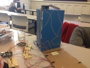
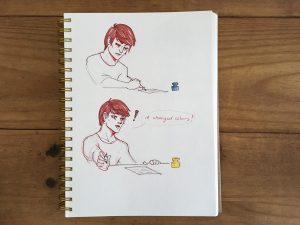
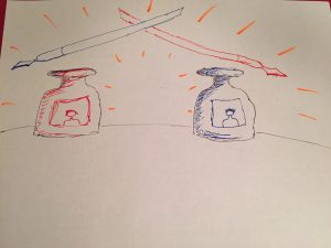
We were inspired by the music of people going caroling from house to house where the visitor is the one that does the singing. But, what if we reverse who does the singing and instead have the house and person’s home do the caroling? Furthermore, what if the person who visits starts a song and then the person who’s home it is (who is answering the door) adds to that song in a duet or collaborative way? That’s what our caroling house does.

How it works:

  • A visitor walks up to the beginning of the path
  • The christmas lights light up the path
  • The visitor steps on the welcome mat
  • A song begins playing
  • The visitor presses the door bell
  • Snow falls from the gutter to create a wintery environment
  • The person who lives at the house answers the door. When they turn the doorknob, the song changes to a different octave adding to the duet.
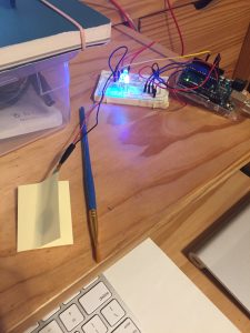
Inputs used:

  • FSR (x3)
  • Potentiometer

Outputs used:

  • 6 LEDs
  • piezo speaker
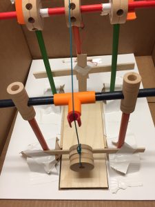
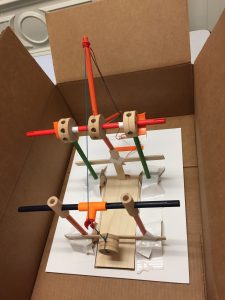
  • servo motor to dump snow from the gutter

Materials used

  • FSR (x3)
  • Potentiometer
  • 6 LEDs
  • Piezo speaker
  • Servo motor
  • 3 Arduinos
  • 4 breadboards
  • 6 220k ohm resistors
  • 4 10k ohm resistor

Doorknob and Welcome Mat Code

// TONES ========================================== // Start by defining the relationship between
 // note, period, & frequency.
 #define C 523
 #define Db 554
 #define D 587 
 #define Eb 622
 #define E 659
 #define f 698 // Does not seem to like capital F
 #define Gb 740
 #define G 783
 #define Ab 830 
 #define A 880
 #define Bb 932
 #define B 988
 #define c_ 1046
 #define dd 1109
 #define d 1175
 #define eb 1244
 #define e 1318
 #define ff 1397
 #define gb 1480
 #define g 1568 
 // Define a special note, 'R', to represent a rest
 #define R 0
 // SETUP ============================================
 // Set up speaker on a PWM pin (digital 9, 10 or 11)
 int speakerOut = 9;
 int FSRPin = A0;
 int potPin = A1;
 int valFSR = 0;
 int valPot = 0;
 int i = 0;
 // Do we want debugging on serial out? 1 for yes, 0 for no
 int DEBUG = 1;
 void setup() {
 pinMode(speakerOut, OUTPUT);
 if (DEBUG) {
 Serial.begin(9600); // Set serial out if we want debugging
 }
 }
 // MELODY and TIMING =======================================
 // melody[] is an array of notes, accompanied by beats[],
 // which sets each note's relative length (higher #, longer note)
 int melody1a[] = {E, E, E,R,
 E, E, E,R,
 E, G, C, D, E, R,
 f, f, f,f, f, E, E,E, E, D ,D,E, D, R, G ,R,
 E, E, E,R,
 E, E, E,R,
 E, G, C, D, E, R,
 f, f, f,f, f, E, E, E, G,G, f, D, C,R, G, R }; 
 
 int melody1b[] = {B, B, B,R,
 B, B, B,R,
 B, D, G, A, B, R,
 C, C, C,C, C, B, B,B, B, D ,D,C, A, R, G ,R,
 B, B, B,R,
 B, B, B,R,
 B, D, G, A, B, R,
 C, C, C,C, C, B, B,B, B, D ,D,C, A, R, G ,R };
 
 //put melody 2a and 2b here 
 int melody2a[] = {E,R, R, R,
 f, E, Eb, E, 
 f, R, R, R, 
 Gb, G, R, R,
 R, A, B, c_, 
 d, c_, B, A, 
 G,R, R, R,
 E,R, R, R,
 f, E, Eb, E, 
 f, R, R, R, 
 Gb, G, R, R,
 R, A, B, c_, 
 d, c_, B, A, 
 G,R, R, R};
 
 int melody2b[] = {A, R, R, R,
 B, A, Ab, A,
 Bb, R, R, R, 
 B, c_, R, R,
 R, d, e, f, 
 g, f, e, d,
 c_, R, R, R,
 A, R, R, R,
 B, A, Ab, A,
 Bb, R, R, R, 
 B, c_, R, R,
 R, d, e, ff, 
 g, ff, e, d,
 c_, R, R, R};
 
// int MAX_COUNT1 = sizeof(melody1) / 2; // Melody length, for looping.
// int MAX_COUNT2 = sizeof(melody2) / 2;
 // Set overall tempo
 long tempo = 10000;
 // Set length of pause between notes
 int pause = 1000;
 // Loop variable to increase Rest length
 int rest_count = 100; //<-BLETCHEROUS HACK; See NOTES
 // Initialize core variables
 int tone_ = 0;
 int beat = 0;
 long duration = 0;
 // PLAY TONE ==============================================
 // Pulse the speaker to play a tone for a particular duration
 void playTone() {
 long elapsed_time = 0;
 if (tone_ > 0) { // if this isn't a Rest beat, while the tone has
 // played less long than 'duration', pulse speaker HIGH and LOW
 while (elapsed_time < duration) {
 digitalWrite(speakerOut,HIGH);
 delayMicroseconds(tone_ / 2);
 // DOWN
 digitalWrite(speakerOut, LOW);
 delayMicroseconds(tone_ / 2);
 // Keep track of how long we pulsed
 elapsed_time += (tone_);
 }
 }
 else { // Rest beat; loop times delay
 for (int j = 0; j < rest_count; j++) { // See NOTE on rest_count
 delayMicroseconds(duration); 
 } 
 } 
 }
 
 void playNote(int melody[]) {
 tone_ = melody[i];
 beat = 50;
 duration = beat * tempo;
 playTone();
 delayMicroseconds(pause);
 }
 
 // LET THE WILD RUMPUS BEGIN =============================
 
 void loop() {
 valFSR = analogRead(FSRPin); // read value from the sensor
 valPot = analogRead(potPin);
// int *melody = melody1; ///fix later
 if (valFSR >= 10 && valFSR < 500 ){ 
 Serial.println(valFSR);
 Serial.println(valPot);
 if (valPot < 10) {
 int *melody = melody1a;
 playNote(melody);
 } else {
 int *melody = melody1b; //move to duet
 playNote(melody);
 }
 }
 if (valFSR >= 500 ){ 
 Serial.println(valFSR);
 Serial.println(valPot);
 if (valPot < 10) {
 int *melody = melody2a;
 playNote(melody);
 } else {
 int *melody = melody2b; //move to duet
 playNote(melody);
 }
 }
// playNote(melody);
 i++;
}
// if (valFSR >= 500) { //second song
// Serial.println(valFSR);
// int *melody = melody1a;
// playNote(melody);
// i++;
// }
// if (i%60 == 0) {
// i = 0;
// }
//}


img_7584

Final Project Proposal – Emotive Watercolor Palette

Final Project Proposal – Emotive Watercolor Palette [better name TBD]

We are interested in collaborative art making. Collaborations simply for the enjoyment of experiencing the creative process with another person, to create a more inclusive environment for non-artists and to redirect the value of art from finished masterpieces to the explorative and failure-driven process. We imagine that collaborative art making would harness the energy/movement/attitudes of your partner which could be extended to include remote collaboration.  The following proposes an Emotive Watercolor Palette to engage partners in painting in a new, collaborative way.

Imagine this scenario: two painters, each with their own an Emotive Watercolor Palette, paintbrush (with FSR and tilt sensors), and a water cup. Partner A is painting and the intensity at which they paint influences the colors available to Partner B. And, vice versa, resulting in a dance between Partner A and Partner B where the actions of one influences the creative process/outcome of the other. Both partners could either be in the same room, or in remote locations*.

Process:

  • Read the level of intensity at which Partner A holds their paintbrush (with FSR and tilt sensors**)
  • Partner B’s watercolor palette will have lids covering each paint color.  These lids will flap up and down at various rates depending on the intensity read in from Partner A’s brush – a faster rate if Partner A is painting with higher intensity and slower rate if Partner B is painting with lower intensity. The flapping lids are meant to indicate life in a rhythmic fashion, similar to playing the keys of a piano or beating a drum.
  • When Partner B needs more paint, they will dip their paint brush into the water cup. This activates a sensor (either photocell or FSR) which sends a signal to the water palette to pause the up and down flapping motion of the paint lids for approximately 1 minute. (This is so Partner B can actually get their brush into the paint color).
  • The paint colors available (because their lids stay open, while others stay closed) will be 3 consecutive colors along the ROYGBIV spectrum which indicate intensity. So, for example:
    • ROY would be open and GBIV would be closed at the highest intensity state. [ROY]GBIV
    • ROYG would be closed and BIV would be open at the lowest intensity state. ROYG[BIV]
    • For a middle intensity, YGB would be open while RO IV would be close. RO[YGB]IV.

This gives the painter a range of colors to work with that all have a similar tone to them.

  • Additionally, a complimentary color would be shown. For example, if [ROY] is open, [B] would also remain open to give Partner B encouragement to use a color that may be out of their comfort zone (this could be an educational tool for novices).
  • Meanwhile, this same process is happening for Partner A.

We plan to make the water color palettes on a wooden box such that the colors from the paint will seep into and color the wood over time. This will serve as an artifact of the intensity state of one’s partner over time.

Team execution:

All team members intend to continue to participate in all aspects of design and creation. Although, we have identified leaders for each aspect to ensure organized development. Dina will lead research, Jake will lead electronics, and Andrea will lead the coding.

* We intend to focus first on synchronous interactions, but plan to consider asynchronous interactions, time permitting.

** We will test the FSR to see if we can detect the degree of the painter’s intensity by pressure on the brush bristles, or the pressure at which someone holds the brush.

Trapdoor Cuckoo Clock

Description:

Our group wanted to attempt an unconventional cuckoo clock, counter to the example we saw in class with the 4-bar joint. Instead of a cuckoo that emerged horizontally from the door, we designed a cuckoo that plunged through a trapdoor instead. The primary mechanism used to move the trapdoor and lower the cuckoo through the opening is a pulley system. As the pulley is pulled in one direction, the trapdoor moves out of the way to reveal an exit. As the pulley is pulled and the trapdoor is moved back, the cuckoo also lowers. The cuckoo is mitigated from falling outside the bounds of the trapdoor exit until the opening is wide enough for it to plunge through. The cuckoo can then continue to be lowered, or reigned back into the clock by pulling the pulley in the opposite direction. The trapdoor is prevented from collapsing on the cuckoo prematurely by means of (1) the distances used in both the strings affixed to the door and the cuckoo, and (2) the rotational distance between the door and the peg that pushes it back into place.

To hold the system in place and direct accurate movement, we have in place four poles around the trapdoor’s perimeter (but not affixed to the trapdoor). These poles are taped securely to the surface of the foam board/clock base. While there are three gears in our structure, only the center one is unrestrained by a foundational support component. For our design, it is imperative that thread lines are measured to have sufficient tension and slack when appropriate. Otherwise, the system will fail. If the support structure also shifts (whether at foundation or at suspension), the system is likely to fail due to the shifting of the trapdoor in and out of place. Also necessary is a wall to prevent the cuckoo from traveling with the trapdoor as it slides back, as opposed to falling through the exit.

We think this cuckoo clock mechanism design is appropriate, considering the majority of cuckoo clocks hang on the wall, and so have room beneath them that can be utilized.

Components Used:

  • 7 gears (4 for foundational support, 2 for suspended support, 1 for pulley system)
  • 1 long stick
  • 2 mid-length sticks
  • 5 short sticks (sizes must be relative; 3 for pulley system)
  • 1 cuckoo (made out of a spool, suspended by string)
  • two cuts of string (1 for the trapdoor, 1 for the cuckoo)
  • 1 relatively large piece of balsa wood for the trapdoor
  • 3 relatively narrow pieces of balsa wood for support/error-prevention
  • 1 T-pipe
  • 2 straight joints with medial socket
  • 1 claw
  • 1 foam board sheet
  • duct tape
  • X-acto knife and cutting board
  • sufficient string for the pulley system


img_6360 img_6359

RR06: VR

As you have experienced the HTC Vive, 1) What was the part of the experience you liked most? How might you enhance or expand the experience? 2) What was the part of your experience you liked least and how might the design team address/improve it?

I observed people this previous week while they interacted with the HTC Vive within virtual reality; however, I have used the HTC Vive before to explore terrains, as well as illustrate in TiltBrush. The experience I liked most was being able to explore environments (essentially, new worlds) within virtual reality, and truly feel like I am there. I’m a gamer with an active imagination, and so I couldn’t help myself from thinking about the worlds I could see, what environments that are currently inaccessible to me would then be accessible. I might try to expand on this aspect of exploration by exploring modes of transportation, and making that experience feel as real as other features are.

The part of my experience I liked the least was actually creating in TiltBrush. I think the concept is fun and allows barriers to be broken down with regard to accessibility to drawing/creativity. Where it breaks for me is the difficulty with depth perception. I don’t know how deep my brush is in this limitless canvas, and that directly affects how my creation will unfold. As a design intervention, aside from visual cues within the virtual environment, I would think a tensile sensor would be helpful on your arm. The further your reach, the more tension/resistance is applied to your arm. I can see how this would be limiting to free form drawing, which is unfortunate. But the lack of depth perception cues when you haven’t assigned a focal point in 3D space (such as a rock, or a model to draw AROUND) is quite frustrating.


Lab07: Crimson Crawler

Description:

I had so much fun assembling this crawler, thinking about the mechanics of a one-legged crawler, and how weight would need to be distributed to get it to move in a linear direction. While hardwood floor doesn’t allow for enough friction between it and the tips of the paperclips, the knit of my scarf produced similar (but slightly better) results. I discovered that my crawler crawls best on a surface with some teeth to it, such as the cover of one of my sketchbooks. Through experimentation I discovered that in order to get it to walk straighter, I needed to reprogram the arduino such that it didn’t have the servomotor have one single sweeping pattern.

Components Used:

  • 1 Arduino
  • 1 Servomotor
  • 1 Breadboard
  • 1 pot (but unused in the sketch below)
  • 1 large paperclip, 1 medium paperclip
  • 1 Futaba servomotor box
  • 1 X-factor nail polish bottle
  • electrical tape

Code:

/*
 * Servo Control Serial
 * modified for TUI October 2007
 * Servo Serial Better
 * -------------------
 *
 * Created 18 October 2006
 * copyleft 2006 Tod E. Kurt <tod@todbot.com>
 * http://todbot.com/
 *
 * adapted from "http://itp.nyu.edu/physcomp/Labs/Servo"
 */
#include <Servo.h>

Servo myservo; // create servo object to control a servo
int servoPin = 7; // Control pin for servo motor

int pos = 0; // variable used to store data from serial port

int minPulse = 0; // minimum pulse width
int maxPulse = 100; // maximum pulse width

void setup() {
 pinMode(servoPin, OUTPUT); // Set servo pin as an output pin
 pos = minPulse; // Set the motor position to the minimum
 Serial.begin(9600); // connect to the serial port
 Serial.println("Servo control program ready");
 myservo.attach(7); // attaches the servo on pin 9 to the servo object
}

void loop() {
 for (pos = minPulse; pos <= maxPulse; pos += 1) { // goes from 0 degrees to 180 degrees
 // in steps of 1 degree
 myservo.write(pos); // tell servo to go to position in variable 'pos'
 delay(7); // waits 7ms for the servo to reach the position
 }
 for (pos = maxPulse; pos >= minPulse; pos -= 1) { // goes from 180 degrees to 0 degrees
 myservo.write(pos); // tell servo to go to position in variable 'pos'
 delay(5); // waits 5ms for the servo to reach the position
 }
}


AND ALSO

/*
 * Servo Control Serial
 * modified for TUI October 2007
 * Servo Serial Better
 * -------------------
 *
 * Created 18 October 2006
 * copyleft 2006 Tod E. Kurt <tod@todbot.com>
 * http://todbot.com/
 *
 * adapted from "http://itp.nyu.edu/physcomp/Labs/Servo"
 */
#include <Servo.h>

Servo myservo; // create servo object to control a servo
int servoPin = 7; // Control pin for servo motor

int pos = 0; // variable used to store data from serial port

int minPulse = 0; // minimum pulse width
int maxPulse = 115; // maximum pulse width
int correction = 55;
int count = 0;

void setup() {
 pinMode(servoPin, OUTPUT); // Set servo pin as an output pin
 pos = minPulse; // Set the motor position to the minimum
 Serial.begin(9600); // connect to the serial port
 Serial.println("Servo control program ready");
 myservo.attach(7); // attaches the servo on pin 9 to the servo object
}

void loop() {
 for (count = 0; count <= 2; count +=1) {
 for (pos = correction; pos <= maxPulse; pos += 1) { // goes from 0 degrees to 180 degrees
 // in steps of 1 degree
 myservo.write(pos); // tell servo to go to position in variable 'pos'
 delay(7); // waits 7ms for the servo to reach the position
 }
 for (pos = maxPulse; pos >= correction; pos -= 1) { // goes from 180 degrees to 0 degrees
 myservo.write(pos); // tell servo to go to position in variable 'pos'
 delay(5); // waits 5ms for the servo to reach the position
 }
}
 for (count = 0; count <= 7; count +=1) {
 for (pos = minPulse; pos <= correction; pos += 1) { // goes from 0 degrees to 180 degrees
 // in steps of 1 degree
 myservo.write(pos); // tell servo to go to position in variable 'pos'
 delay(7); // waits 7ms for the servo to reach the position
 }
 for (pos = correction; pos >= minPulse; pos -= 1) { // goes from 180 degrees to 0 degrees
 myservo.write(pos); // tell servo to go to position in variable 'pos'
 delay(5); // waits 5ms for the servo to reach the position
 }
}


}


img_6347-mov img_6346-mov

RR05: Hobonichi Techo Daily Planner

I tried to transition to planning my days in a digital calendar; however, I found my experience lackluster, and soon found myself not tracking my days at all. The lack of a customizable experience — to the extent that I felt like it was easily identified as my planner and not anyone else’s — pulled me back to paper planners. But, my former Moleskine planners were ill designed for sufficient, flexible realestate on a page. I looked into creating my own bullet journal, but lack the time to make one completely to my liking.

So, I did some research and found myself purchasing a Hobonichi Techo Daily Planner. It’s a daily planner that is made in Japan that is rather compact, with Tomoe River paper (which before I ordered the planner meant absolutely nothing to me, because I had never experienced writing on it before), and bound in a way such that it lays flat. I was very nervous with this purchase, having gone from store to local store hunting for a copy for me to touch, maybe run a pen over. I am very particular about how my notebooks feel as I use them, and how much of a struggle it is to write close to the binding. My previous planners did not hold ink very well, or forced a structure that did not suit my lifestyle. These things you unfortunately do not realize until after attempting to use the planner for a while.

Immediately, when the journal arrived, I ran my fingers over the cover, the Tomoe river paper, and tested the paper with a fountain pen. To my pleasant surprise, the ink did not feather nor bleed through onto the next page. I was thrilled to find a resilient and compact planner with just enough printed structure that would suit my commuter life, and I have to say I am sold for life.

House from Up

Description:

I decided to channel energy from the Disney movie Up. I programmed the piezo to output the theme song from the movie when someone steps on the doorstep of the house. Let’s pretend the house is up in the sky, per the cotton of cloud beneath it. :}

Components Used:

  • 1 Arduino
  • 1 Resistor (10kΩ)
  • 1 Breadboard
  • 1 piezo
  • 1 FSR potentiometer
  • 1 3D printed house (out of PLA)
  • cotton (to simulate a cloud)

Code:

/* Play Melody
 * -----------
 *
 * Program to play melodies stored in an array, it requires to know
 * about timing issues and about how to play tones.
 *
 * The calculation of the tones is made following the mathematical
 * operation:
 *
 * timeHigh = 1/(2 * toneFrequency) = period / 2
 *
 * where the different tones are described as in the table:
 *
 * note frequency period PW (timeHigh) 
 * c 261 Hz 3830 1915 
 * d 294 Hz 3400 1700 
 * e 329 Hz 3038 1519 
 * f 349 Hz 2864 1432 
 * g 392 Hz 2550 1275 
 * a 440 Hz 2272 1136 
 * b 493 Hz 2028 1014 
 * C 523 Hz 1912 956
 *
 * (cleft) 2005 D. Cuartielles for K3
 */

int ledPin = 13;
int potPin = A0;
int speakerOut = 7; 
//byte names[] = {'c', 'd', 'e', 'f', 'g', 'a', 'b', 'C'}; 
//int tones[] = {1915, 1700, 1519, 1432, 1275, 1136, 1014, 956};

byte names[] ={ 'c', 'd', 'e', 'f', 'g', 'a', 'b', 'C', 'D', 'E', 'F', 'G', 'A', 'B'}; 
unsigned int tones[] = { 1915, 1700, 1519, 1432, 1275, 1136, 1014, 956, 852, 759, 716, 639, 568, 506};

byte melody[] = "3F3A3F9E5p3F3A3F5E2p3D3F3D4C2p3D8A8G1p3D8A8G1p3D1p9D8p";

int val = 0;
int count = 0;
int count2 = 0;
int count3 = 0;
int MAX_COUNT = 28;
int statePin = LOW;

void setup() {
// pinMode(ledPin, OUTPUT); 
 pinMode(speakerOut, OUTPUT);
}

void loop() {
 digitalWrite(speakerOut, LOW);
 val = analogRead(potPin); // read value from the sensor
if (val > 0 ){ 
 for (count = 0; count < MAX_COUNT; count++) {
 statePin = !statePin;
 digitalWrite(ledPin, statePin);
 for (count3 = 0; count3 <= (melody[count*2] - 48) * 30; count3++) {
 for (count2=0;count2<15;count2++) {
 if (names[count2] == melody[count*2 + 1]) { 
 digitalWrite(speakerOut,HIGH);
 delayMicroseconds(tones[count2]);
 digitalWrite(speakerOut, LOW);
 delayMicroseconds(tones[count2]);
 } 
 if (melody[count*2 + 1] == 'p') {
 // make a pause of a certain size
 digitalWrite(speakerOut, 0);
 delayMicroseconds(500);
 }
 }
 }
 }
}
}

Up Melody

Seamlessly Personalized Fashion

I have been thinking about this general idea for a while now. The idea that the clothes we wear are indicative of our own personal style, but that they can be made furthermore personalized (and intimate), is a compelling art and fashion piece. The fabric would tell a story that is specific to the person wearing it, and perhaps not understandable without them providing the context. I see a visualization — of paths walked throughout a day, a few days, a week; of the number of hugs received plotted on a plane; of brisk and lull moments depicted through color — showcased on the fabric of the material. In this vision, the garment is usually a sweater, but could potentially take other forms (scarf, pants, tee shirts). In this vision, the visualization grows quietly, denoting aspects of the person’s time wearing it without interrupting the person’s day. This way, the wearer may go about their business, getting lost and consumed in their daily activities, able to remember and reflect on the day once they remove the garment from their back. Additionally, because the garment is worn, it is inherently public. And in this way, the wearer is choosing to narrate a bit of their personal, unique story to an audience — any audience that crosses their path. Again, the audience may be unaware of what the plot may be, but it could be a probe that makes them curious (even if it is momentary, a stranger wonders about the life of another).

Pressure Painting (Lab 04)

Description:

It is often ill-advised for a painter to apply much tension to their brush strokes. Not only does it harm the integrity of the bristles, but it also constricts the artist’s technique and ultimately the nature of their work. For this lab, I used an FSR potentiometer and Processing to indicate when there’s too much tension applied to the brush in a brushstroke. The LEDs also blink at a heightened pace when too much pressure is applied, as to alert the artist if they’re too preoccupied looking down at what they are painting to notice the color on the screen.

Components Used:

  • 1 Arduino
  • 3 LEDs (red, green, and blue)
  • 3 Resistors (220Ω)
  • 1 Resistor (10kΩ)
  • 1 Breadboard
  • 1 FSR Potentiometer
  • 1 post-it sheet

Code:

/*
 This example is meant to read three analog sensors (potentiometers are easiest)
 and sends their values serially. The Processing and Max/MSP programs at the bottom
 take those three values and use them to change the background color of the screen.

 [Dina's addition:
 In the event of only one potentiometer being attached, all three analog inputs
 will be affected in the same way.]

 The circuit:
 * potentiometers attached to analog inputs 0, 1, and 2

 http://www.arduino.cc/en/Tutorial/VirtualColorMixer

 created 2 Dec 2006
 by David A. Mellis
 modified 30 Aug 2011
 by Tom Igoe and Scott Fitzgerald
 modified on 24 Sept 2016
 by Dina Bseiso

 This example code is in the public domain.

 */

int sensorPin = A0; // select the input pin for the potentiometer for pulse
int sensorValue = 0; // variable to store the value coming from the sensor


const int redledPin = 9;
const int blueledPin = 10;
const int greenledPin = 11; // select the pin for the LED

void setup() {
 // declare the ledPin as an OUTPUT:
 pinMode(redledPin, OUTPUT);
 pinMode(blueledPin, OUTPUT);
 pinMode(greenledPin, OUTPUT);
 Serial.begin(9600);
}

void loop() {
 Serial.print(analogRead(redledPin));
 Serial.print(",");
 Serial.print(analogRead(greenledPin));
 Serial.print(",");
 Serial.println(analogRead(blueledPin));
 // read the value from the sensor:
 sensorValue = analogRead(sensorPin);
 // turn the ledPin on
 digitalWrite(redledPin, HIGH);
 digitalWrite(blueledPin, HIGH);
 digitalWrite(greenledPin, HIGH); 
 // stop the program for <sensorValue> milliseconds:
 delay(sensorValue);
 // turn the ledPin off:
 digitalWrite(redledPin, LOW);
 digitalWrite(blueledPin, LOW);
 digitalWrite(greenledPin, LOW);
 // stop the program for for <sensorValue> milliseconds:
 delay(sensorValue);
}

/* PROCESSING SKETCH
 * Arduino Painting Tension
 * (from Arduino Ball, modified 2008, and then by Dina on 2016)
 * ---------------------- 
 *
 * Change the color on the screen depending on
 * the amount of pressure applied to an FSR.
 *
 * Created 24 September 2016
 * Dina Bseiso
 */
import processing.serial.*;
// Change this to the portname your Arduino board
String portname = "/dev/cu.usbmodem1441"; // or "COM5"
Serial myPort;
String buf="";
int cr = 13; // ASCII return == 13
int lf = 10; // ASCII linefeed == 10


float redValue = 0; // red value
float greenValue = 0; // green value
float blueValue = 0; // blue value

int serialVal = 0;
int serialValAmplified = 0;


void setup() {
 size(300,300);
 frameRate(10);
 smooth();
 ellipseMode(CENTER);
 background(40,40,40);
 noStroke();
 myPort = new Serial(this, portname, 9600); 
}

void draw() {
 // set the background color with the color values:
 background(redValue, greenValue, blueValue);
}

// called whenever serial data arrives
void serialEvent(Serial myPort) {
 // get the ASCII string:
 String inString = myPort.readStringUntil('\n');
 println(inString);

 if (inString != null) {
 // trim off any whitespace:
 inString = trim(inString);
 // split the string on the commas and convert the
 // resulting substrings into an integer array:
 float[] colors = float(split(inString, ","));
 // if the array has at least three elements, you know
 // you got the whole thing. Put the numbers in the
 // color variables:
 if (colors.length >=3) {
 //println(colors);
 // map them to the range 0-255:
 if (colors[0] >= 700) {
 blueValue = map(colors[2], 0, 1023, 150, 255);
 greenValue = map(colors[1], 1023, 0, 75, 150);
 redValue = map(colors[0], 1023, 0, 0, 75);
 }
 else if (colors[0] >= 300) {
 greenValue = map(colors[1], 1023, 0, 150, 255);
 blueValue = map(colors[2], 0, 1023, 75, 150);
 redValue = map(colors[0], 1023, 0, 75, 150);
 }
 else if (colors[0] >= 0) {
 redValue = map(colors[0], 1023, 0, 150, 255);
 greenValue = map(colors[1], 0, 1023, 75, 175);
 blueValue = map(colors[2], 0, 1023, 0, 75);
 }
 }
 }
}

img_6255

Pressure Painting