Description
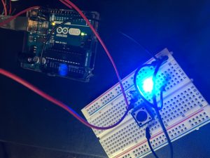
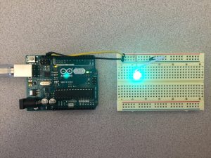
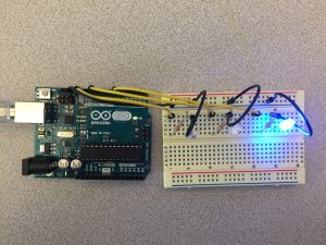
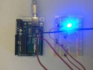
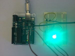
After having the LED blink in accordance with the preloaded program, I proceeded to write my own. I wanted the LED to glow at its maximum brightness, slowly fade to zero and then rise again. I used a for() loop for accomplishing this. Also, I used analogWrite instead of digitalWrite so I can have varying levels of brightness instead of a binary HIGH or LOW.
Components
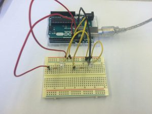
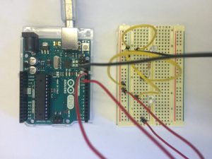
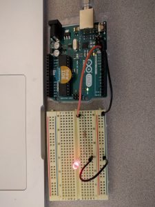
- 1 Arduino Uno
- 1 Breadboard
- 1 LED
- Jumper wires
- 1 USB cable
- 1 220 ohm resistor
Code
int green = 11;
void setup() {
pinMode(green, OUTPUT); // initialize analog pin 11 as an output.
}
void loop() {
int x = 1;
for (int i = 0; i > -1; i = i + x)
{
analogWrite(green, i);
if (i == 255) // if the LED reaches maximum brightness,
x = -1; // start dimming it by 1 point every second
delay(100);
}
}