Lab 1 · Fading Lights

Description


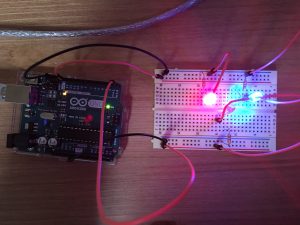
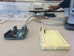
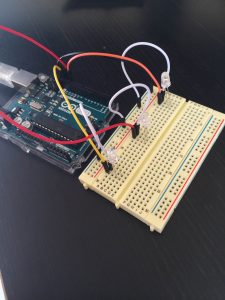
I wanted to test multiple simultaneous LEDs blinking at different rates and came across an example that faded the LED lights. Using Arduino and the red, green, and blue LEDs, I connected pins 9, 10, and 11 to the breadboard; via resistors, these three pins connected to the blue, green, and red LEDs, respectively. I made the blue LED fade the most rapidly, fading completely in 250 milliseconds. The green LED is intermediate, fading in 750 milliseconds. The red LED is the slowest, fading in 2550 milliseconds. After a light fades, it restarts back at full brightness.

Originally, I used pins 11, 12, and 13, but only the blue LED, connected to pin 11, would fade while the green and red LEDs would remain their initialized value. After a few Google searches, I saw that only certain pins read analogWrite(), and so I adjusted my pins accordingly.


Components


  • 1 · Arduino Uno
  • 1 · Breadboard
  • 3 · LEDs
  • 3 · 220Ω Resistors
  • 7 · Jumper wires


Code


/*
Blink
Turns on an LED on for one second, then off for one second, repeatedly.

This example code is in the public domain.
*/

int rVolt, ri = 5;
int gVolt, gi = 15;
int bVolt, bi = 51;

// The setup function runs once when you press reset or power the board.
void setup() {
// Initialize the digital pin as an output.
pinMode(11, OUTPUT);
pinMode(10, OUTPUT);
pinMode(9, OUTPUT);
}

// The loop function runs over and over again forever.
void loop() {
if (rVolt == 0 || rVolt == 255) {ri = -ri;};
if (gVolt == 0 || gVolt == 255) {gi = -gi;};
if (bVolt == 0 || bVolt == 255) {bi = -bi;};
rVolt += ri;
gVolt += gi;
bVolt += bi;
analogWrite(11, rVolt);
analogWrite(10, gVolt);
analogWrite(9, bVolt);
delay(50);
}


Image


Kate Lee · Lab 1

Arduino, can we be friends?

Arduino, I learned a little about you today- more than our initial meeting. Some basics, like you were in my downloads and I should move you to my applications. Other things like this, simple things but mainly how to better friends- that you read a certain language, and I can read the notes in grey- and somehow translation. I didn’t try many things, but I changed the code, subtracting two zeros the first time, and adding 2 the second time- which I liked, because it was slow enough, like an affirmation, we could do this together- communicate.

BlinkenLights

description:
I tried making a few variations of light blinking on/off rhythms but the possibilities are endless, so I went with speeds/pause that had some contrast: 2 blips of 0.1 second, and a 1-second, followed by a 2 second pause.


components:

1 Arduino

1 LED

1 Resistor(220Ω)

1 Breadboard

code

void setup() {
// initialize digital pin 13 as an output.
pinMode(13, OUTPUT);
}

// the loop function runs over and over again forever
void loop() {
digitalWrite(13, HIGH); // turn the LED on (HIGH is the voltage level)
delay(100); // wait for .1 second
digitalWrite(13, LOW); // turn the LED off by making the voltage LOW
delay(100); // wait for .1 second
digitalWrite(13, HIGH); // turn the LED on (HIGH is the voltage level)
delay(100); // wait for .1 second
digitalWrite(13, LOW); // turn the LED off by making the voltage LOW
delay(100); // wait for .1 second
digitalWrite(13, HIGH); // turn the LED on (HIGH is the voltage level)
delay(1000); // wait for a second
digitalWrite(13, LOW); // turn the LED off by making the voltage LOW
delay(2000); // wait for 2 seconds
}


Lab1 – LED Lights & Arduino

Description
I used Arduino with three LED lights. I have used the red, the blue and the green LED lights. I have placed the blue and red on the left side of the breadboard and placed the green on the right side of the breadboard. To achieve this, I have used two grounds and two different pins (pin 13 and pin 0). The blue and red lights will turn on for one second and turn off for .5 second, then the green LED will turn on for 2 seconds and turn off for .5 seconds. The loop will restart after green LED turns off. I have uploaded the code to ensure the timing is right. Use the black wires for grounds and the orange wires for the rest of the pins. I have also used three resistors, each LED light uses one.
Components
  • 1 Arduino
  • 3  LED (Red, Blue, Green)
  • 3 Resistor (220Ω)
  • 1 Breadboard
  • 2 black wires for ground
  • 5 orange wires for the inputs

Code

int pin = 13;
int pin0 = 0;
void setup() {
  // setting up the two pins
  pinMode(pin, OUTPUT);
  pinMode(pin0, OUTPUT);
}
void loop() {
  // light up for 1 sec
  digitalWrite(pin, HIGH); //0 VOLTS OR 5
  delay(1000);
  digitalWrite(pin, LOW);
  // turn off for .5 sec
  delay(500);
  digitalWrite(pin0, HIGH); //0 VOLTS OR 5
  // light up for 2 sec
  delay(2000);
  digitalWrite(pin0, LOW);
  // turn off for .5 sec
  delay(500);
}
Photo
Both Red and Blue lights turning on

Both Red and Blue lights turning on

Green LED lights on

Green LED lights on

All lights off

All lights off

Blink and No Blink

Description

For this lab, I used 2 LEDs and wrote up my sketch such that one would blink and one would always be on.

Components

  • 1 Arduino
  • 2 LEDs
  • 1 Resistor (220Ω)
  • 1 Breadboard

Code

/*
Blink
Turns on an LED on for one second, then off for one second, repeatedly.

Most Arduinos have an on-board LED you can control. On the Uno and
Leonardo, it is attached to digital pin 13. If you’re unsure what
pin the on-board LED is connected to on your Arduino model, check
the documentation at http://www.arduino.cc

This example code is in the public domain.

modified 8 May 2014
by Scott Fitzgerald
*/
// the setup function runs once when you press reset or power the board
void setup() {
// initialize digital pin 12 and 13 as an output.
pinMode(13, OUTPUT);
pinMode(12, OUTPUT);
}

// the loop function runs over and over again forever
void loop() {
digitalWrite(12, HIGH); // turn the LED on pin 12 on
digitalWrite(13, HIGH); // turn the LED on pin 13 on (HIGH is the voltage level)
delay(100); // wait for a second
digitalWrite(13, LOW); // turn the LED on pin 13 off by making the voltage LOW
delay(100); // wait for a second
}

Lab 01

Description

I used Arduino with a red LED. I edited the sketch code to turn on the LED for 10 seconds and then off for 2 seconds. Uploaded the code and took pictures of the result.

Components

  • 1 Arduino
  • 1 LED
  • 1 Resistor (220Ω)
  • 1 Breadboard

Code

/*
 Blink
 Turns on an LED on for one second, then off for one second, repeatedly.

Most Arduinos have an on-board LED you can control. On the Uno and
 Leonardo, it is attached to digital pin 13. If you're unsure what
 pin the on-board LED is connected to on your Arduino model, check
 the documentation at http://www.arduino.cc

This example code is in the public domain.

modified 8 May 2014
 by Scott Fitzgerald
 */


// the setup function runs once when you press reset or power the board
void setup() {
 // initialize digital pin 13 as an output.
 pinMode(13, OUTPUT);
}

// the loop function runs over and over again forever
void loop() {
 digitalWrite(13, HIGH); // turn the LED on (HIGH is the voltage level)
 delay(10000); // wait for a second
 digitalWrite(13, LOW); // turn the LED off by making the voltage LOW
 delay(2000); // wait for a second
}

Frightened Computing (pt 2)

Oops–hit “post” before adding my second jpeg! The curled fingers in the following image should be read as the visual accompaniment to a user yelling at their arduino:

Frightened Computing

Description:
Chapter two of Acting With Technology begins by offering that “…recent trends in interaction design include emotion in design, extending usability to include the “pleasurability” of interactive products (Norman 2004) . . . affective computing (Picard 1997), affective design (Aboulafia and Bannon 2004), [and] autonomous characters (Tomlinson 2005) (Dourish 25). Using two LEDs instead of one introduces affective possibility into an otherwise inanimate series of wires and boards by alluding to a pair of eyes; and by coding the lights to temporarily turn off when the circuit is yelled at one creates perhaps the most basic relationship possible—but a relationship nonetheless, and one that a user should probably find emotionally moving. Relationships between humans and computers are often filled with hostility—a computer appears to not be behaving, and so we express our frustration at it. But what if computers responded to yelling with exhibits of fear, meekness, and regret?


Components:
• 1 Arduino Uno
• 1 Breadboard
• 2 LEDs
• Jumper Wires
• 1 Battery pack (4 AA)
• 1 SparkFun Electret Microphone Breakout


Code:
const int sampleWindow = 250; //250 MS sample width
unsigned int loudNoise;

void setup()
{
pinMode(12, OUTPUT); //these control the LED eyes
pinMode(2, OUTPUT);
Serial.begin(9600);
}

void loop()
{

{
digitalWrite(12, HIGH); //these make the eyes “on” by default
digitalWrite(2, HIGH);
delay(0);
}

unsigned long start= millis(); // start of sample window
unsigned int peakToPeak = 0; // peak-to-peak level

unsigned int signalMax = 0;
unsigned int signalMin = 1024;

while (millis() – start < sampleWindow) // collecting data for 250 MS (can be changed)
{
loudNoise = analogRead(0);
if (loudNoise < 1024) // { if (loudNoise > signalMax) // if there’s a loud noise, save the loud value
{
signalMax = loudNoise;
}
else if (loudNoise < signalMin) // if there’s not a loud noise, don’t save the loud value { signalMin = loudNoise; } } } peakToPeak = signalMax – signalMin; // max – min = peak-peak amplitude double volts = (peakToPeak * 3.3) / 1024; // convert to volts Serial.println(volts); // to know if the mic is working if (volts >=1.0)
{
digitalWrite(2, LOW);
digitalWrite(12, LOW); //eyes shut off
delay(2000); // for a certain amount of time (though this could be modified for more expressive behavior)
Serial.println(“YELLING AT ME”);
}
else
{
digitalWrite(12, LOW);
digitalWrite(2, LOW); //not yetlling at me
}
}

Sing happy birthday with LEDs

Description

Learning about blinking LED using Arduino, I wanted to create something that could deliver value/benefit to an observer. A thought came to my mind: sing a song for him/her! By varying the tempo, I was able to make the LEDs blink along with the song, Happy Birthday.  One obstacle I found was that the LED bulbs were too bright to a naked eye and, thus, are in need of appropriate/decorative cover.


Components

  • 1 Arduino Uno
  • 1 Breadboard
  • 2 LEDs
  • Jumper wires
  • 1 USB cable
  • 1 220 ohm resistor

Code

// the setup function runs once when you press reset or power the board
void setup() {
// initialize digital pin 13 as an output.
pinMode(13, OUTPUT);
}

// the loop function runs over and over again forever
void loop() {
digitalWrite(13, HIGH); // Happy birthday to you
delay(375);
digitalWrite(13, LOW);
delay(50);
digitalWrite(13, HIGH); //turn the LED on (HIGH is the voltage level)
delay(125); // wait for a second
digitalWrite(13, LOW); // turn the LED off by making the voltage LOW
delay(50); // wait for a second
digitalWrite(13, HIGH);
delay(500);
digitalWrite(13, LOW);
delay(50);
digitalWrite(13, HIGH);
delay(500);
digitalWrite(13, LOW);
delay(50);
digitalWrite(13, HIGH);
delay(1000);
digitalWrite(13, LOW);
delay(50);

digitalWrite(13, HIGH); // Happy birthday to you
delay(375);
digitalWrite(13, LOW);
delay(50);
digitalWrite(13, HIGH);
delay(125);
digitalWrite(13, LOW);
delay(50);
digitalWrite(13, HIGH);
delay(500);
digitalWrite(13, LOW);
delay(50);
digitalWrite(13, HIGH);
delay(500);
digitalWrite(13, LOW);
delay(50);
digitalWrite(13, HIGH);
delay(1000);
digitalWrite(13, LOW);
delay(50);

digitalWrite(13, HIGH); // Happy birthday dear my friend
delay(375);
digitalWrite(13, LOW);
delay(50);
digitalWrite(13, HIGH);
delay(125);
digitalWrite(13, LOW);
delay(50);
digitalWrite(13, HIGH);
delay(500);
digitalWrite(13, LOW);
delay(50);
digitalWrite(13, HIGH);
delay(500);
digitalWrite(13, LOW);
delay(50);
digitalWrite(13, HIGH);
delay(500);
digitalWrite(13, LOW);
delay(50);
delay(500);
digitalWrite(13, LOW);
delay(50);
digitalWrite(13, HIGH);
delay(500);
digitalWrite(13, LOW);
delay(50);

digitalWrite(13, HIGH); // Happy birthday to you
delay(375);
digitalWrite(13, LOW);
delay(50);
digitalWrite(13, HIGH);
delay(125);
digitalWrite(13, LOW);
delay(50);
digitalWrite(13, HIGH);
delay(500);
digitalWrite(13, LOW);
delay(50);
digitalWrite(13, HIGH);
delay(500);
digitalWrite(13, LOW);
delay(50);
digitalWrite(13, HIGH);
delay(1000);
digitalWrite(13, LOW);
delay(50);
}


image1 image2

Who needs auto-tune when you have an Arduino board and LEDs?

When I learned that this project entailed LEDs, the first thought that came to mind was how I could combine the main task of flashing an LED and relate it to music. Rihanna’s “Disturbia” has a prominent introductory beat that I thought would be the perfect complement to a flashing light. However, rather than using just one light, I chose to program three LEDs to flash at different rates depending on which part of the chorus it was.

First, I connected one jumper wire from GND on the Arduino board to the negative rail on the breadboard. I then connected three other jumper wires from rows 10-13 on the Arduino board to a positive row on the breadboard. Next, I used the remaining three jumper wires to act as resistors for the wires connected to the Arduino board by connecting one end to the negative rail and the other end above the other wire on the breadboard (view photos for clarification). Finally, I connected the LEDs to the breadboard by putting the positive side (longer leg) below the wire connected to the Arduino board and I put the negative side (shorter leg) under the port that connects the negative rail. Now, the physical components of my board were ready. The final step was to write code that would make the lights flash to the beat of the song. After using code provided by Arduino and tweaking the HIGH and LOW voltage levels for each light, I was able to create a light show that corresponded to Rihanna’s “Disturbia”.

Components used:

  • 1 Arduino Uno
  • 1 Breadboard
  • 3 LEDs
  • 7 jumper wires
  • 1 USB cable

Code:
int ledgreen = 13; //(green)
int ledblue = 12; //(blue)
int ledred = 11; //(red)

// the setup routine runs once when you press reset:
void setup()
{
// initialize the digital pin as an output.
pinMode(ledgreen, OUTPUT);
pinMode(ledblue, OUTPUT);
pinMode(ledred, OUTPUT);
}

// the loop routine runs over and over again forever:
void loop()
{
digitalWrite(ledgreen, HIGH); // turn the LED on (HIGH is the voltage level)
delay(240); // wait for a second
digitalWrite(ledgreen, LOW); // turn the LED off by making the voltage LOW
delay(240);
digitalWrite(ledgreen, HIGH); // turn the LED on (HIGH is the voltage level)
delay(240); // wait for a second
digitalWrite(ledgreen, LOW); // turn the LED off by making the voltage LOW
delay(240);
digitalWrite(ledblue, HIGH);
delay(150);
digitalWrite(ledblue, LOW);
delay(225);
digitalWrite(ledred, HIGH);
delay(100);
digitalWrite(ledred, LOW);
delay(250);
digitalWrite(ledblue, HIGH);
delay(250);
digitalWrite(ledblue, LOW);
delay(250);
digitalWrite(ledblue, HIGH);
delay(250);
digitalWrite(ledblue, LOW);
delay(250);
digitalWrite(ledred, HIGH);
delay(200);
digitalWrite(ledred, LOW);
delay(150);
digitalWrite(ledblue, HIGH);
delay(250);
digitalWrite(ledblue, LOW);
delay(175);
digitalWrite(ledred, HIGH);
delay(200);
digitalWrite(ledred, LOW);
delay(225);

}

Arduino Arduino 2