RR06 – HTC Vive and VR experiences

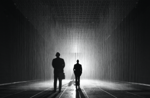
The HTC Vive experience was significantly more impressive than I had expected. Having tried out an early version of the Oculus Rift, I was expecting incremental improvements over that system, rather than the enormous gains made by the Vive, especially in terms of interactivity and realism. It passed the “bat-twitch” test for me, as Wired called it. For instance, in the whale encounter, I was a bit worried what was going to happen when it flapped its tail, and I think I flinched quite a bit. Although my favorite part was the TiltBrush, and being able to draw with any number of tools and really move around within my creation. It feels like such a boon for creativity, to be able to create something and see it immediately (like the best parts of coding, being able to test whether your code works immediately, and see results), vs. say, painting with oils or photography with film.

I think the areas for enhancement are tied to the areas I found lacking: namely, having a sense for where I was in space, and wanting to stop worrying about crashing into something or tripping over the cable near my feet. Those worries kept me from being physically free in a way that would translate to the VR experience. I also think it could be improved by making it more social. It was fun to have people’s voices present from the room in my experience, and to have reassurance that I wasn’t going to hurt myself, but I haven’t yet tried any VR experiences that allow for multiple people, and I think that would really enhance the experience. Those seem to already exist, based on the Wired article, so it would be neat to get to try them. I think improvements in processing and battery power will soon be able to address some of the issues with physicality and cables and tethering.

One additional thing that I do worry about, but didn’t while having the experience:

“One of the underappreciated aspects of synthetic reality is that every virtual world is potentially a total surveillance state. By definition, everything inside a VR or MR world is tracked. After all, the more precisely and comprehensively your body and your behavior are tracked, the better your experience will be.”

As someone at the I School, I feel it’s important for us to pay attention to the issue of privacy and surveillance, as well. Do these teams have privacy practitioners on them? Should we be creating a framework here, or at least be thinking about one?

Lab 06 – DC motor-powered barber pole

Description:
For this lab, I wanted to test how much power our little DC motors have. Since it’s acknowledged that they don’t have much torque, I didn’t want to choose something too heavy, but I did want to extend the range of the spinning motion so that it would be visible from far away. Looking around my apartment, I happened to have a poster tube sitting around, which I realized would make the perfect object: it’s long but slender, doesn’t weigh much but it stable, and is round, so I could fairly easily spin it with the motor without getting too much vibration.

So, I created a monochrome version of a barber’s pole:
molly-lab06

First, I used the potentiometer as the speed control so that I could “lock in” a spin speed:
img_1248

But after that, I wanted to try out using the FSR so that I could control the spin while holding the motor, so that I’d have I/O coincidence. That’s what I’ll be demonstrating in class.

One interesting observation I had was that with a heavy-ish weight, the motor takes quite a bit of “revving” to get to a level of power sufficient to overcome the inertia. And then, after removing power, my barber pole keeps spinning for quite some time. Interesting to watch it in action.

Components:

  • Arduino Uno
  • breadboard
  • 1 DC motor
  • 1 Transistor
  • 1 Diode
  • 2 resistors (one 1KΩ, one 10KΩ)
  • 1 FSR (or potentiometer)
  • 1 poster tube, decorated
  • piece of cork (to provide friction and hold the motor in place on the end of the tube)
  • battery pack
  • two AA batteries
  • jumper wires


Code:
(This is the final code, using the FSR rather than the potentiometer.)


int potPin = 0; // select the input pin for the potentiometer/FSR
int motorPin = 9; // select the pin for the Motor
int val = 0; // variable to store the value coming from the sensor
void setup() {
Serial.begin(9600);
}
void loop() {
val = analogRead(potPin); // read the value from the sensor, between 0 - 1023
val = map(val, 0, 1023, 0, 255);
Serial.println(val);
analogWrite(motorPin, val); // analogWrite can be between 0-255
}

Thoughtless acts around town

It’s interesting to notice some of the design interventions that have already been applied around campus to deter the very thoughtless acts that I was looking for. For one, all of the trash cans I’ve noticed have a peaked or domed design, such that pieces of trash do not balance on top of the trash can. I imagine this is so that people will actually put their trash INSIDE the trash can rather than on top of it. However, that doesn’t quite stop people from leaving trash wherever they can find a supporting base for it:

img_1238

Including in a tree!

img_1245


One of the things I do regularly is wrap my teabag string around the handle of my mug:

img_1237

I hadn’t thought of this as a thoughtless act until seeing it in one of the Pinterest streams. But it accomplishes my goal of not having the teabag become lost inside the mug when I pour hot water over it. Baristas tend to do the same thing: if they put a teabag in your commuter mug, they’ll screw the lid on with the teabag label hanging out. One potential design update is to give commuter mugs a small notch where the teabag string can be held securely. However, a potentially better one is just to have a tea strainer inside the mug, which some designs already accomplish. That works well for both loose-leaf tea and bagged tea.


While shopping for groceries last night (and TJ’s was as crowded as I’ve ever seen it—it was right before the debate, and Sunday night, and everybody and their mother wanted to get groceries for the week. Suffice it to say, I was waiting for a while with a rather heavy basket. So I placed it on the floor, and pushed it along with my foot when the line would move forward.

img_1246

I see this also in airport lines, when people push their heavy luggage along the floor rather than picking it up and carrying it forward as the line moves along. A design improvement could be a place for people to keep handbaskets or small but heavy items up at waist level as they wait in line, for instance with a bar-height shelf. It would also serve to keep the line orderly.

Best birthday card ever!

Description:

For this lab, I decided to make the best birthday card ever. For those who just can’t get enough of having people sing them Happy Birthday (or those who like to celebrate for an entire month—long after their friends have grown tired of singing Happy Birthday to them), this birthday card is for them. Every time the special birthday lady or gentleman opens the card, it plays them Happy Birthday. It uses a photocell to determine when the card is opened, and I used a modified notebook to stand in for the card because I don’t actually have any birthday cards lying around, sadly. Thankfully for those in the same room, the card will stop playing the melody, but will start again from the beginning once opened again.

Components:

  • Arduino Uno
  • Breadboard
  • 1 10kΩ resistor
  • 1 photocell
  • 1 piezo speaker
  • jumper cables
  • birthday card

img_1228

img_1229

Code:

// TUI Lab 05 - Molly
// Happy birthday melody sourced from http://forum.arduino.cc/index.php?topic=178460.0

int speakerPin = 9;
int photoPin = A1;
int length = 28; // the number of notes
char notes[] = "GGAGcB GGAGdc GGxecBA yyecdc";
int beats[] = { 2, 2, 8, 8, 8, 16, 1, 2, 2, 8, 8,8, 16, 1, 2,2,8,8,8,8,16, 1,2,2,8,8,8,16 };
int tempo = 150;
int val = 0;

void playTone(int tone, int duration) {
for (long i = 0; i < duration * 1000L; i += tone * 2) {
digitalWrite(speakerPin, HIGH);
delayMicroseconds(tone);
digitalWrite(speakerPin, LOW);
delayMicroseconds(tone);
}
}

void playNote(char note, int duration) {
char names[] = {'C', 'D', 'E', 'F', 'G', 'A', 'B',
'c', 'd', 'e', 'f', 'g', 'a', 'b',
'x', 'y' };

int tones[] = { 1915, 1700, 1519, 1432, 1275, 1136, 1014,
956, 834, 765, 593, 468, 346, 224,
655 , 715 };
int SPEE = 5;

// play the tone corresponding to the note name
for (int i = 0; i < 17; i++) {
if (names[i] == note) {
int newduration = duration/SPEE;
playTone(tones[i], newduration);
}
}
}

void setup() {
pinMode(speakerPin, OUTPUT);
Serial.begin(9600);
}

void loop() {
Serial.print("Value:");
Serial.print(analogRead(photoPin));
while (analogRead(photoPin) > 200) {
for (int i = 0; i < length; i++) {
if (notes[i] == ' ' and analogRead(photoPin) < 200) {
delay(beats[i] * tempo); // rest
}
else if (analogRead(photoPin) < 200) {
playNote(notes[i], beats[i] * tempo);
}
else break;
// pause between notes
delay(tempo);
}
}
}

When a piece of paper isn’t just a piece of paper

One of the objects that most surprised and delighted me was the program guide to an architectural/industrial design exhibition for Heatherwick Studio at the LA County Museum of Art a few years back. Normally, one goes to a museum or gallery show and grabs a program to hold while walking through the exhibit, only to return it to the docent at the end or toss it carelessly into the trash after returning home. As Blauvelt would call it, this is the “ritual of use.” The guides may reference artworks, may even include reproductions of the art on the walls, but they are just that—reproductions—that no one would confuse with the real thing (no cargo cult there, no one would be duped). A program guide is merely a functional artifact that assists a visitor in identifying and understanding the works of art, which appear on the walls or within the gallery.

But not from this show. When I returned home, I hung the gallery guide on my wall.

Of course, it wasn’t “art” per se, but the experience of obtaining the gallery guide lent it enough emotional heft that I held onto the guide, rolled it like a small poster and cushioned it in my purse on the way home, and later mounted it on my wall. It even traveled with me when I moved from LA to Berkeley.

A printed guide for an art show is an entirely everyday object, so why all the fuss? To begin with, obtaining the gallery guide required work. There was an industrial-sized dispenser, with rolls and rolls of uncut paper guides, which had to be unrolled by hand, with the help of the room-sized dispenser. The docent merely watched as visitors unrolled and trimmed their own guides:

heatherwick-gallery-guide
(photo from http://www.carolinebanks.co.uk/wp-content/uploads/Thomas-Heatherwick-VA-4.jpg)

At the end of that process, you had your own personal gallery guide. It felt like it was meant entirely for you, because you had had ownership in the creation of that single artifact. On the front side of the guide was a summary of the works present in the exhibition. On the back side, a repeating graphic design of the inciting questions that led the studio to create the various works of art/design present in the exhibition. Thus, the guide included both the genesis and output, two ends of the spectrum. It elucidated all parts of the process. In this sense, it gave more meaning to each of the artifacts present in the show; I, as a visitor, had a small sense of ownership over each artifact, because I had an insight into the mental model of the creator. The questions were provocative, but they dealt with aspects of the everyday. Can mistakes in aluminum extrusion create public seating? Can a chair be made completely symmetrical? And so on. This gallery guide, while technically only a long piece of cardstock paper, completely overturned my conception of the limits of program guides and the opportunities for creativity in even the most mundane and quotidian items. Instead of becoming a piece of trash, the guide became a portable reminder of the exhibition, an artistic decoration, and a multifunctional piece of paper—both referential and provocative.


* The entire show was fabulous and I recommend you check out Heatherwick Studio’s work, especially two versions of seating: the Extrusion series and the Spun chairs. Two vastly different takes on public seating. Both are beautiful, functional, and amazing, and the studio has work ranging in scale from a handbag to a city park.

Lab 4: Pots + Processing

Description:
For this lab, I wanted to focus on transferring data from multiple variables and multiple sensors from Arduino into Processing. I was less concerned with what visualization to make than how to give someone more control over it and how to allow it to have multiple input streams. Because the photocell was too sensitive for easy daylight use, I stuck with the FSR for my main sensor. I kept the LED within the circuit so that it could provide me with a backup indication of the pressure on my sensor, and then I added three pots back into the circuit. Each pot controls RGB values, and can be adjusted independently. The FSR I covered with a stress-reliever type foam ball with a slit cut into it. This allowed me to slip it over the FSR and it could act as a diffuser for the squeeze pressure on the ball. This way I can squeeze on the ball in general and still affect the FSR value. The visualization responds quickly to changes in pressure and color. (The nice thing about using RGB values instead of RGB LEDs is that we can actually get additive white onscreen!)

I also ran into some problems in the making of this visualization: Processing was not correctly reading in the final value from the serial input. After troubleshooting to determine that the problem was indeed within Processing, I added in a dummy value as a final value in my Arduino output as a quick solution. I also had an issue where I was getting a “USB device drawing too much power” from my computer. After trying a few solutions, I realized that two of my pots had shifted on the desk and were touching bare wire at one spot. After rearranging and separating them, I was able to get the circuit working again.

Here is a GIF of my animation (I am squeezing with one hand and adjusting the pots with the other hand):
lab04-molly

And my circuit:
img_1221

img_1220

Components:
– Arduino Uno
– breadboard
– 1 LED
– 1 220 ohm resistor
– 1 FSR
– 1 10 ohm resistor
– 3 potentiometers
– jumper wires

Arduino Code:

/*
Lab04 - Sensing: Photocells and FSR
Molly Mahar

*/

int FSRcellReading = 0; // initialize value read from the FSR
int ledPin = 11;
int LEDbrightness = 0;
int rPot = A1;
int rVal = 0;
int gPot = A2;
int gVal = 0;
int bPot = A3;
int bVal = 0;

void setup() {
// initialize serial communications at 9600 bps:
Serial.begin(9600);
// declare the led pin(s) as output:
pinMode(ledPin, OUTPUT);
}

void loop() {
// this will map the LED brightness according to the pressure placed on the FSR:
FSRcellReading = analogRead(A0);
//now we have to map 0-1023 to 0-255 since thats the range analogWrite uses.
LEDbrightness = map(FSRcellReading, 0, 1023, 0, 255);
// Also want to read in the values from the three pots, and map those to 0-255 RGB values:
rVal = map(analogRead(rPot), 0, 1023, 0, 255);
gVal = map(analogRead(gPot), 0, 1023, 0, 255);
bVal = map(analogRead(bPot), 0, 1023, 0, 255);
analogWrite(ledPin, LEDbrightness); // PWM the LED with the pot value (divided by 4 to fit in a byte)
//construct a message to Processing with multiple values in arduino
//we can't just send a string from here since it only officially understands 'bytes'
// Got help in this instance from this post: https://processing.org/discourse/beta/num_1193069410.html
Serial.print(FSRcellReading);
Serial.print(",");
Serial.print(rVal);
Serial.print(",");
Serial.print(gVal);
Serial.print(",");
Serial.print(bVal);
Serial.print(",");
// Not sure why I'm having this problem, but Processing was somehow not reading the last value?
// I checked in the serial monitor and it was getting sent from Arduino
// So I'm adding a final value into the serial printout, so that all my rgb values will be read in Processing
Serial.print(0,DEC);
Serial.print("|");
//Serial.println([FSRcellReading, rVal, gVal, bVal]);
delay(100); // pause at that level before looping through again
}

Processing Code:

/* PROCESSING SKETCH
* Based on the original ball code by Noura Howell
* Modified for Lab 4 by Molly Mahar
*/
import processing.serial.*;
String portname = "/dev/cu.usbmodem1421"; // or "COM5"
Serial port;
String buf="";
int cr = 13; // ASCII return == 13
int lf = 10; // ASCII linefeed == 10
//int serialVal = 0;
int ballSize = 0;
int rVal = 0;
int gVal = 0;
int bVal = 0;

void setup() {
size(700,700);
frameRate(10);
smooth();
background(40,40,40);
noStroke();
port = new Serial(this, portname, 9600);
}

void draw() {
// erase the screen
background(40, 40, 40);
// draw the ball
fill(rVal, gVal, bVal);
ellipse(350,350,ballSize,ballSize);
}

//read the message in Processing
//original version of this code (then edited) from: https://processing.org/discourse/beta/num_1193069410.html
void serialEvent(Serial myPort){
String myString = myPort.readStringUntil(124); //the ascii value of the "|" character
if(myString != null ){
myString = trim(myString); //remove whitespace around our values
int inputs[] = int(split(myString, ','));
//now assign your values in processing
if(inputs.length == 5){
ballSize = inputs[0];
rVal = inputs[1];
gVal = inputs[2];
bVal = inputs[3];
}
}
}

Sensory information in calm computing

First off, I found it very interesting that the authors of Calm Technology chose to discuss glass office windows as an example—I found it very fitting, but surprising! However, it helped me bring the concept of calm computing more into my everyday life, since I don’t regularly encounter items like the Live Wire piece.

One aspect I think is missing from the examples is the concept of progress. One of the reasons, for instance, that users might have a dashboard is to know what their schedule is, what is upcoming, or what time it is. Is there a way to use ambient media to signal progress along some sort of continuum? Currently there are many variations tackling that problem using GUIs and traditional patterns, but it didn’t seem that any of the examples covered it. I take it as an assumption that one would need “progress” to be in the center of their attention in order to grasp it, but why? After all, we can judge progress in terms of distance out of our peripheral vision, or when there are tangible items within our view. But I’m having trouble calling to mind an example of calm computing that incorporates notions of progress when the TUI is in the periphery rather than central.

I’d also be curious to discuss how to bring in our other senses to calm computing. For instance, vision and hearing play a big role in the examples: one is looking at a dashboard, seeing or hearing a Live Wire, or looking through or hearing people through a glass window. But what about taste? What about touch or skin conductance? (These are, after all, classified as TUIs—but there wasn’t any discussion of their tangible properties.) What about temperature variations? And what about smell? Those senses always alert us to potential danger—original ambient media, as another student pointed out in reference to smoke detectors—but how are artists and creators incorporating them into calm computing as a way to communicate meaning and information?

Fishkin’s Taxonomy and the Rain Room

One UI that I wondered about (and struggled with how to characterize), is that of the Rain Room. The Rain Room is an embodied, immersive art exhibit that allows a visitor to enter a room and be surrounded by falling water, without getting wet. The room itself responds to the presence of humans and adjusts the rainfall accordingly, so that each human has a small envelope within which they can stand and not be caught “in the rain.”

RainRoom

When reading Fishkin, the Rain Room seemed initially like an example of calm computing. My main rationale for classifying it this way was because the human participants don’t use their hands for controlling the rain—something Fishkin emphasizes as one of the requirements of a TUI rather than calm computing. However, there are many TUIs that do not rely on the hands for the input (someone else’s example of Dance, Dance Revolution comes to mind, where input comes from participants’ feet, mainly). Thus, classification of the Rain Room seemed somewhat problematic: the human participants do control the rain, in the sense that their physical motion is the input that the computer system detects, to then alter output accordingly. However, they do not control the rain with their hands, which seems to be a requirement. Yet, all of Fishkin’s examples of calm computing seem to revolve around systems that do not take any kind of direct input from humans, and the Rain Room most definitely does. If it were an example of calm computing, I would posit that it fits into the “nearby” category of embodiment (which Fishkin couldn’t find offer an example of), and perhaps the verb level of metaphor (after all, moving to avoid the rain in the rain room is like avoiding the rain in real life). Yet, in some ways it seems like “full” metaphor to me, because there is none. To avoid the rain in the Rain Room is to avoid the rain. You are physically being acted upon, experiencing the computers output, in the same manner as in real life.

However, in the end this doesn’t seem to me to fit clearly into any of the taxonomical categories—I would suggest modifying the taxonomy to include a broader definition of input than just hand manipulation, so that the Rain Room could be classified as a TUI rather than calm computing. Much like some of the other students mentioned, it might be helpful for us to discuss more deeply where to draw the line between “what is a TUI” and “what isn’t a TUI,” especially as our computing devices rely more and more on physical manipulation to accomplish our goals.

Lab 03 – Color Switcher

Description:

For this lab, I wanted to play around with all of the options available to me. I began with the pot controlling the blinking rate, then added a potentiometer to control the fade. After working through a minor issue with the digitalOut vs. analogOut that prevented the fade from working properly with the blinking, I was able to figure out how to make the two potentiometers play nice with each other.

Then I decided that I wanted to use the third potentiometer to control the mapping between the three LEDs—to use the rotation as a signal for which LED should be lit and which should be dark. So I added the third potentiometer and then did some research (and used the serial monitor) to read what values were being output by that new pot. I then set four increments, and had each individual LED light up for the first three (low values would be red, mid-low values would be green, mid-high values would be blue). Then I set the highest value to map to having all three LEDs lit at the same time. By using the serial monitor to troubleshoot from the beginning, I was able to get it to work with a minimum of trouble. So my first pot controls the blink rate, my second pot controls the fade level, and the third pot controls which LEDs are lit.

circuit board and LEDs

Components:

  • Arduino Uno
  • Breadboard
  • 3 potentiometers
  • 3 LEDs (red, green, blue)
  • 3 220Ω resistors
  • jumper wires
  • USB cable
  • computer

Code:


// EXTRA CREDIT CODE: mapping a third potentiometer so that I can control individual LEDs to fire one at a time,
// or have all three fire at once (when third pot is maxed out)

int fadepotPin = A1; // Analog input pin that the fade potentiometer is attached to
int fadepotValue = 0; // value read from the fade pot
int blinkpotPin = A0; // Analog input pin that the blink potentiometer is attached to
int blinkpotValue = 0; // value read from the blink pot
int mappingPin = A2; // this will be the one that maps rotation to LED color
int mappingValue = 0; // initially set the rotational mapping value to zero
int redledPin = 11;
int greenledPin = 10;
int blueledPin = 9;

void setup() {
// initialize serial communications at 9600 bps:
Serial.begin(9600);
// declare the led pins as output:
pinMode(redledPin, OUTPUT);
pinMode(blueledPin, OUTPUT);
pinMode(greenledPin, OUTPUT);
}

void loop() {
fadepotValue = analogRead(fadepotPin); // read the fade pot value
blinkpotValue = analogRead(blinkpotPin); // read the blink pot value
mappingValue = analogRead(mappingPin); // read the value on the mapping pot

// turn on only the LED(s) that correspond to the value of the third pot
// minimum value for blue, middle values for green, and max value for red
// then that will turn on the LEDs according to the fade value and blink value

// print the results to the serial monitor:
Serial.print("mappingValue = ");
Serial.print(mappingValue);
Serial.print("\n");

if (mappingValue < 255) { analogWrite(redledPin, fadepotValue/4); // PWM the LED with the pot value (divided by 4 to fit in a byte) delay(blinkpotValue); // delay by the blink pot value in milliseconds digitalWrite(redledPin, LOW); // then blink the LEDs off } else if (mappingValue >= 255 and mappingValue <; 610) { analogWrite(greenledPin, fadepotValue/4); // PWM the LED with the pot value (divided by 4 to fit in a byte) delay(blinkpotValue); // delay by the blink pot value in milliseconds digitalWrite(greenledPin, LOW); // then blink the LEDs off } else if (mappingValue >= 610 and mappingValue < 770) { analogWrite(blueledPin, fadepotValue/4); // PWM the LED with the pot value (divided by 4 to fit in a byte) delay(blinkpotValue); // delay by the blink pot value in milliseconds digitalWrite(blueledPin, LOW); // then blink the LEDs off } else if (mappingValue >= 770) {
analogWrite(redledPin, fadepotValue/4); // PWM the LED with the pot value (divided by 4 to fit in a byte)
analogWrite(blueledPin, fadepotValue/4);
analogWrite(greenledPin, fadepotValue/4);
delay(blinkpotValue); // delay by the blink pot value in milliseconds
digitalWrite(redledPin, LOW); // then blink the LEDs off
digitalWrite(blueledPin, LOW);
digitalWrite(greenledPin, LOW);
}
delay(blinkpotValue); // pause before blinking back on (also allows loop to run and pots to be adjusted)
}

LED Diffusion

Description:

After experimenting with and testing out the serial monitor functionality of the Arduino environment and watching the fading color change program work, I chose cone coffee filters as my diffuser of choice. This was after much experimentation–initially, I’d had the three LEDs spaced a few rows apart on the breadboard, but this didn’t allow them to mix very well. So first, I modified my breadboard so that all the LEDs were touching each other.

IMG_1185

I tried diffusing with the large cotton balls in class, but those didn’t allow enough light to pass through. I then tried different configurations of coffee filters, lightbulb housings, plastic storage containers, and more. The cone-type coffee filters worked best for me because they maintained structure around the LEDs, and having two stacked on top of each other allowed for more uniform diffusion.

IMG_1184

I then modified the code so that a user can press r, g, or b and the LEDs will change based on the following equation: (#key presses/10)*255. This gives the percentage of light, and then applies that to the full value of 255.

Components:

  • Arduino Uno
  • Breadboard
  • 3 LEDs (rgb)
  • 3 220Ω Resistors
  • 2 Coffee filters
  • jumper wires
  • USB cable
  • laptop

Code:

/* Modified on 9/7/16 by Molly Mahar
*
* Serial RGB LED
* ---------------
* Serial commands control the brightness of R,G,B LEDs
*
* Command structure is "<colorCode><colorVal>", where "colorCode" is
* one of "r","g",or "b" and "colorVal" is a number 0 to 255.
* E.g. "r0" turns the red LED off.
* "g127" turns the green LED to half brightness
* "b64" turns the blue LED to 1/4 brightness
*
* Created 18 October 2006
* copyleft 2006 Tod E. Kurt <tod@todbot.com
* http://todbot.com/
*/

char serInString[100]; // array that will hold the different bytes of the string. 100=100characters;
// -> you must state how long the array will be else it won't work properly
char colorCode;
int colorVal;

int redPin = 9; // Red LED, connected to digital pin 9
int greenPin = 10; // Green LED, connected to digital pin 10
int bluePin = 11; // Blue LED, connected to digital pin 11

void setup() {
pinMode(redPin, OUTPUT); // sets the pins as output
pinMode(greenPin, OUTPUT);
pinMode(bluePin, OUTPUT);
Serial.begin(9600);
analogWrite(redPin, 127); // set them all to mid brightness
analogWrite(greenPin, 127); // set them all to mid brightness
analogWrite(bluePin, 127); // set them all to mid brightness
Serial.println("enter color command (e.g. pressing 'r' 5 times will put red LED at 50% brightness) :");
}

void loop () {
// clear the string
memset(serInString, 0, 100);
//read the serial port and create a string out of what you read
readSerialString(serInString);

colorCode = serInString[0];
if( colorCode == 'r' || colorCode == 'g' || colorCode == 'b' ) {
//colorVal = atoi(serInString+1);
colorVal = 0;
for (int i=0; i<strlen(serInString); i++) {
if( colorCode == 'r' || colorCode == 'g' || colorCode == 'b' )
{
colorVal += 1;
}
}
if (strlen(serInString) > 10){
colorVal = 0;
}

//colorVal = strlen(serInString);
colorVal = (colorVal/10.0)*255;
Serial.print("setting color ");
Serial.print(colorCode);
Serial.print(" to ");
Serial.print(colorVal);
Serial.println();
serInString[0] = 0; // indicates we've used this string
if(colorCode == 'r')
analogWrite(redPin, colorVal);
else if(colorCode == 'g')
analogWrite(greenPin, colorVal);
else if(colorCode == 'b')
analogWrite(bluePin, colorVal);
}

delay(100); // wait a bit, for serial data
}

//read a string from the serial and store it in an array
//you must supply the array variable
void readSerialString (char *strArray) {
int i = 0;
if(!Serial.available()) {
return;
}
while (Serial.available()) {
strArray[i] = Serial.read();
i++;
}
}