Memento – Final Project Proposal

Team Memento
Group: Fay, Daniel, Michelle

Materials
Arduino Uno (x2)
Nitinol Wire (purchased, ordered, arriving Friday)
Bluetooth Shield (purchased, ordered, arriving Saturday) (x2)
Arduino Uno sensors pack kit (Grove Starter Kit Plus – https://www.seeedstudio.com/grove-starter-kit-plus-p-1294.html ) (already have) (x2)
FS/button, Sound output, Temp sensor, sound input sensor, LED, Sound sensor
Accelerometer (do not have, looking for resource) (x2)

Project Description:
We are building on top our midterm project Memento. Memento is a pair of personal devices used between two friends or family members. For the final project, we have added a third component, a shape-changing object that will react towards the interaction between the two personal devices and represent the relationship journey. We are using Nitinol Wire (wire with memory muscle) to change the shapes of objects that will symbolize the status of the relationship.

The idea is simple: I give my best friend one of these devices and i keep the other for myself. We keep the shape-changing sculptures on our desks or workspaces, and we carry around our little “sensor” eggs. Whenever we hang out or interact with each other, our sculptures grow and change. When we don’t hang out, our sculptures display that we haven’t seen each other in a while.

Our interactions may change the sculpture in a variety of ways: when we talk a lot, our sculpture could make little sounds. When we both push the button when we’re together, there will be a visual hint sent to the paired device, and our sculpture could have elements or flowers “bloom” or a tree “grow.” And when we shake the device when hanging out together, the different levels of shaking inputs will enable different intensity of output of the device. When we both go to the same place, such as a cafe or a gym, the paired device will capture the same location information through beacon bluetooth and return visual hints.

This is an ambient way for us to collect aspects of our friendships and display it in a fun and interactive way.

Nitinol Wire Inspiration:
Nitinol Engine: https://www.youtube.com/watch?v=3MfTJVAtx6w
Watch How Smart Parts Self-Assemble: https://www.youtube.com/watch?v=GIEhi_sAkU8
More Memory Wire Experiment: https://www.youtube.com/watch?v=JKBM9my5eOA
Responsive Panel: https://www.youtube.com/watch?v=teI7baA9_1o

VR Experience

What I love most about VR experience is that it’s actually an “experience” itself. Going to different applications with HTC Vive brings me to different realities. This is drastically different than web experiences where most of the website gives me similar experiences. On the web, we are mostly just absorbing or contributing information on the network. With VR, the focus with information (images/texts,numbers) is lessened by something that’s more grand, an overall experience. I would love to enhance/expand the experience of VR by making more connection with the physical reality, which is basically what Magicleap is trying to do, creating a mixed reality.

The part of the experience I like the least is the headset, it makes my eyes and face sweaty and the wires would occasionally block my way. Making it wireless and making the headset less tangible would enhance the experience more. Also, if I pay a lot of attention to my peripheral sight then I can still gain a peak of the physical reality, which is distracting… removing such burden would also help the experience!

The Chopstick Bot

To make a crawler, the first thing that came into my mind was chopsticks. So I gather a few chopsticks, break them, and them try to put them together in a way that would make the single-legged servo motor crawl. It took some observation and reiteration. I used a lot of tapes and a few coins to adjust the balance. Now this robot is really crawling.. but not in a straight line.. It seems to be moving towards Northwest…

Video

Arduino Code

#include //add servo library

Servo myservo;

int pos = 0; // variable to store the servo position

void setup() {
myservo.attach(9); // attaches the servo on pin 9 to the servo object
}

void loop() {
for (pos = 0; pos <= 180; pos += 1) { // goes from 0 degrees to 180 degrees // in steps of 1 degree myservo.write(pos); // tell servo to go to position in variable 'pos' delay(4); // waits 15ms for the servo to reach the position } delay(200); for (pos = 180; pos >= 0; pos -= 1) { // goes from 180 degrees to 0 degrees
myservo.write(pos); // tell servo to go to position in variable 'pos'
delay(4); // waits 15ms for the servo to reach the position
}
delay(200);
}

Sunny Doll + Weather Art Dashboard

For this assignment, I have connected to a weather API that would return the temperature of the city I’m searching for. I’ve made a list of cities in a list and a for loop that would request temperature for the cities every few seconds. The motor is attached to the sunny doll, however, my motor is currently broken so I can’t show the video here. I’ve attached the picture of sunny doll though. The concept is that if a city is hot the motor will spin the doll faster and spin it slower if it’s colder. Sunny doll is a popular item in Japan that people hang on the brink of their roof as a prayer of good weather.

I’ve also connected arduino with processing that would make sine waves of warm/cool color based on the temperature. I’ve attached the video link as below.

Weather Art Dashboard Youtube Video

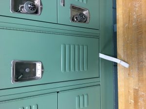
Sunny Doll Made with Napkin…Will have face by tomorrow
img_0970

Python Code

import pyowm
import time
import serial
# Code to add widgets will go here...

#setting up serial communication
ser = serial.Serial('/dev/cu.usbmodem1411', 9600)
#creating pyowm object
owm = pyowm.OWM(API_key='37ec6df9d804fe26229ccf5d4bfb9a28')
#get address
while True:
cityID = [(4570707, 'Berkeley'), (3602359, 'Sandy Bay'), (285570, 'Kuwait'), (2205218,'Fiji'), (1259110,'Qadian'), (6362039,'Montesa'),
(2514896,'Lopera'), (1668341, 'Taipei'), (4930956,'Boston'), (2643743, 'London'),
(1850147, 'Tokyo'), (734198,'Sokhos'), (5128638, 'New York'), (192950, 'Kenya'),
(5861900, 'Fairbanks'), (1822029, 'Stoeng Treng'), (2656877, 'Astley'), (3345279, 'Price Town'),
(256606, 'Nea Kios')]

cityName = ['Berkeley', 'Sandy Bay', 'Kuwait', 'Fiji', 'Qadian', 'Montesa',
'Lopera', 'Taipei', 'Boston', 'London',
'Tokyo', 'Sokhos', 'New York', 'Kenya', 'Fairbanks', 'Stoeng Treng',
'Astley', 'Price Town', 'Nea Kios']

for city in cityID:
observation = owm.weather_at_id(city[0])
print("city: " + str(city[1]))
w = observation.get_weather()
temp = w.get_temperature('celsius')
temp = temp['temp']
print temp
if int(temp) >= 20:
print 'HOT'
ser.write(b'' + str(255) + str(city[1]))
elif int(temp) < 20 & int(temp) >= 10:
print 'Meh'
ser.write(b'' + str(120)+ str(city[1]))
elif int(temp) < 10: print 'COLD' ser.write(b'' + str(80)+ str(city[1])) time.sleep(1)

Arduino Code

/*
* one pot fades one motor
* modified version of AnalogInput
* by DojoDave
* http://www.arduino.cc/en/Tutorial/AnalogInput
* Modified again by dave
*/
float data;
int potPin = 0; // select the input pin for the potentiometer
int motorPin = 9; // select the pin for the Motor
int val = 0; // variable to store the value coming from the sensor
String str = "";

void setup() {
Serial.begin(9600);
}
void loop() {
// val = analogRead(potPin); // read the value from the sensor, between 0 - 1024
// Serial.println(val);
// analogWrite(motorPin, val); // analogWrite can be between 0-255
if(Serial.available() > 0) {
data = Serial.parseFloat();
Serial.println(data);
analogWrite(motorPin, data); // analogWrite can be between 0-255
}
}

Processing Code

import processing.serial.*;
Serial port;
String portname = "/dev/cu.usbmodem1411";
int SerialVal = 0;
String myString = null;
int xspacing = 16; // How far apart should each horizontal location be spaced
int w; // Width of entire wave
int r = 255;
int warmIncrement = 0;
int coldIncrement = 0;
int g = 255;
int b = 255;
String buf="";
int cr = 13; // ASCII return == 13
int lf = 10; // ASCII linefeed == 10
float theta = 0.0; // Start angle at 0
float amplitude = 500.0; // Height of wave
float period = 500.0; // How many pixels before the wave repeats
float dx; // Value for incrementing X, a function of period and xspacing
float[] yvalues; // Using an array to store height values for the wave
String[] cityName = {"Berkeley", "Sandy Bay", "Kuwait", "Fiji", "Qadian", "Montesa",
"Lopera", "Taipei", "Boston", "London", "Tokyo", "Sokhos", "New York", "Kenya",
"Fairbanks", "Stoeng Treng", "Astley", "Price Town", "Nea Kios"};
int cityIndex = 0;

void setup() {
size(1300, 800);
w = width+16;
dx = (TWO_PI / period) * xspacing;
yvalues = new float[w/xspacing];

port = new Serial(this, portname, 9600);
port.bufferUntil('\n');
}

void draw() {
while (port.available() > 0) {
myString = port.readStringUntil(lf);
if (myString != null) {
print(myString); // Prints String
SerialVal = int(myString); // Converts and prints float
if (SerialVal == 255) {
//textSize(100);
//fill(190, 190, 190);
//text(cityName[cityIndex], 500, 400);
//cityIndex += 1;
r = 255;
g = 50 + warmIncrement;
b = 0 + warmIncrement;
warmIncrement += 50;
if (warmIncrement > 255){
warmIncrement = 0;
}
} else if (SerialVal == 120) {
//textSize(100);
//fill(190, 190, 190);
//text(cityName[cityIndex], 500, 400);
//cityIndex += 1;
r = 190;
g = 190;
b = 190;
} else {
//textSize(100);
//fill(190, 190, 190);
//text(cityName[cityIndex], 500, 400);
//cityIndex += 1;
r = 0 + coldIncrement;
g = 180 + coldIncrement;
b = 255;
coldIncrement += 50;
if (coldIncrement > 255){
coldIncrement = 0;
}
}
println("val="+SerialVal);
}
}
calcWave();
renderWave();
}

void calcWave() {
// Increment theta (try different values for 'angular velocity' here
theta += 0.02;
// For every x value, calculate a y value with sine function
float x = theta;
for (int i = 0; i < yvalues.length; i++) { yvalues[i] = sin(x)*amplitude; x+=dx; } } void renderWave() { noStroke(); fill(r, g, b); // A simple way to draw the wave with an ellipse at each location for (int x = 0; x < yvalues.length; x++) { ellipse(x*xspacing, height/2+yvalues[x], 16, 16); } }

Thoughtless Act in a Locker Room

This is a thoughtless act I sometimes commit when I go to the rsf. Since there are so many different lockers sometimes it’s hard for me to remember which locker I’ve locked my bags with. So I would leave the tail of my backpack out for me to identify later. I think it’s interesting to share because it’s a pretty common problems for lots of people at the locker room and the lockers are not designed to be remember easily. This offers a new design opportunity.. The locker could have colors on them to go along with the numbers!

img_0944

Ode to Joy (While In Space)

I continued with what I made with my last lab. I want to incorporated music into the visual I made. So I worked on making Processing and Arduino to talk to each other by establishing a handshake between them.

Now, I can use my FSR to control the gravity of the bouncing balls. And Processing will process the gravity values into 0 and 1 and feed it back to Arduino. Arduino will control the speed of the music. The music being played is Ode to Joy. The music will play slower when gravity is set to zero!

Arduino Code

/* Photocell simple testing sketch.

Connect one end of the photocell to 5V, the other end to Analog 0.
Then connect one end of a 10K resistor from Analog 0 to ground
Connect LED from pin 11 through a resistor to ground
For more information see http://learn.adafruit.com/photocells */

int photocellPin = 0; // the cell and 10K pulldown are connected to a0
int photocellReading; // the analog reading from the sensor divider
int LEDpin = 11; // connect Red LED to pin 11 (PWM pin)
int LEDbrightness; //
int val;
int buzzerPin = 7;
#define NOTE_C6 1047
#define NOTE_D6 1157
#define NOTE_E6 1319
#define NOTE_F6 1397
#define NOTE_G6 1568
#define NOTE_A6 1760
#define NOTE_B6 1976
#define NOTE_C7 2093

void setup(void) {
// We'll send debugging information via the Serial monitor
Serial.begin(9600);
establishContact(); // send a byte to establish contact until receiver responds
}

void loop(void) {
photocellReading = analogRead(photocellPin);

// LED gets brighter the darker it is at the sensor
// that means we have to -invert- the reading from 0-1023 back to 1023-0
photocellReading = 1023 - photocellReading;
//now we have to map 0-1023 to 0-255 since thats the range analogWrite uses
// LEDbrightness = map(photocellReading, 0, 1023, 255, 0);
// analogWrite(LEDpin, LEDbrightness);
Serial.println(photocellReading);
delay(100);
if (Serial.available()>0)
{ // If data is available to read,
val = Serial.read(); // read it and store it in val
}
if (val == '1')
{
tone(buzzerPin, NOTE_A6, 100);
delay(100);
tone(buzzerPin, NOTE_A6, 100);
delay(100);
tone(buzzerPin, NOTE_B6, 100);
delay(100);
tone(buzzerPin, NOTE_G6, 100);
delay(100);
tone(buzzerPin, NOTE_A6, 100);
delay(100);
tone(buzzerPin, NOTE_B6, 100);
delay(100);
tone(buzzerPin, NOTE_C7, 100);
delay(100);
tone(buzzerPin, NOTE_B6, 100);
delay(100);
tone(buzzerPin, NOTE_G6, 100);
delay(100);
tone(buzzerPin, NOTE_A6, 100);
delay(100);
tone(buzzerPin, NOTE_B6, 100);
delay(100);
tone(buzzerPin, NOTE_C7, 100);
delay(100);
tone(buzzerPin, NOTE_B6, 100);
delay(100);
tone(buzzerPin, NOTE_A6, 100);
delay(100);
tone(buzzerPin, NOTE_G6, 100);
delay(100);
tone(buzzerPin, NOTE_A6, 100);
delay(100);
} else {
tone(buzzerPin, NOTE_A6, 100);
delay(200);
tone(buzzerPin, NOTE_A6, 100);
delay(200);
tone(buzzerPin, NOTE_B6, 100);
delay(200);
tone(buzzerPin, NOTE_G6, 100);
delay(200);
tone(buzzerPin, NOTE_A6, 100);
delay(200);
tone(buzzerPin, NOTE_B6, 100);
delay(200);
tone(buzzerPin, NOTE_C7, 100);
delay(200);
tone(buzzerPin, NOTE_B6, 100);
delay(200);
tone(buzzerPin, NOTE_G6, 100);
delay(200);
tone(buzzerPin, NOTE_A6, 100);
delay(200);
tone(buzzerPin, NOTE_B6, 100);
delay(200);
tone(buzzerPin, NOTE_C7, 100);
delay(200);
tone(buzzerPin, NOTE_B6, 100);
delay(200);
tone(buzzerPin, NOTE_A6, 100);
delay(200);
tone(buzzerPin, NOTE_G6, 100);
delay(200);
tone(buzzerPin, NOTE_A6, 100);
delay(200);
}
}

void establishContact() {
while (Serial.available() <= 0) { Serial.println("A"); // send a capital A delay(300); } }

Processing Code

import processing.serial.*;
import processing.sound.*;

// Change this to the portname your Arduino board
String portname = "/dev/cu.usbmodem1411"; // or "COM5"
Serial port;
String buf="";
int cr = 13; // ASCII return == 13
int lf = 10; // ASCII linefeed == 10
int SerialVal = 0;
float r = 0;
float g = 0;
float b = 0;

int numBalls = 30;
float spring = 0.05;
float gravity = 0.03;
float friction = -0.9;
Ball[] balls = new Ball[numBalls];

int barWidth = 5;
int lastBar = -1;

// since we're doing serial handshaking,
// we need to check if we've heard from the microcontroller
boolean firstContact = false;

void setup() {
size(1500, 800);
for (int i = 0; i < numBalls; i++) { balls[i] = new Ball(random(width), random(height), random(30, 70), i, balls); } noStroke(); port = new Serial(this, portname, 9600); } void draw() { background(r, g ,b); for (Ball ball : balls) { ball.collide(); ball.move(); ball.display(); } if (keyPressed == true && keyCode == UP) { spring += 0.01; } else if (keyPressed == true && keyCode == DOWN) { spring -= 0.01; } else if (keyPressed == true && key == 'r') { r += 10; } else if (keyPressed == true && key == 'R') { r -= 10; } else if (keyPressed == true && key == 'g') { g += 10; } else if (keyPressed == true && key == 'G') { g -= 10; } else if (keyPressed == true && key == 'b') { b += 10; } else if (keyPressed == true && key == 'B') { b -= 10; } else if (keyPressed == true && key == 'S' || key == 's') { friction = -0.9; spring = 0.05; r=0; g=0; b=0; } int whichBar = mouseX / barWidth; if (whichBar != lastBar) { int barX = whichBar * barWidth; fill(barX, mouseY, 66); rect(barX, 0, barWidth, height); lastBar = whichBar; } } class Ball { float x, y; float diameter; float vx = 0; float vy = 0; int id; Ball[] others; Ball(float xin, float yin, float din, int idin, Ball[] oin) { x = xin; y = yin; diameter = din; id = idin; others = oin; } void collide() { for (int i = id + 1; i < numBalls; i++) { float dx = others[i].x - x; float dy = others[i].y - y; float distance = sqrt(dx*dx + dy*dy); float minDist = others[i].diameter/2 + diameter/2; if (distance < minDist) { float angle = atan2(dy, dx); float targetX = x + cos(angle) * minDist; float targetY = y + sin(angle) * minDist; float ax = (targetX - others[i].x) * spring; float ay = (targetY - others[i].y) * spring; vx -= ax; vy -= ay; others[i].vx += ax; others[i].vy += ay; } } } void move() { vy += gravity; x += vx; y += vy; if (x + diameter/2 > width) {
x = width - diameter/2;
vx *= friction;
}
else if (x - diameter/2 < 0) { x = diameter/2; vx *= friction; } if (y + diameter/2 > height) {
y = height - diameter/2;
vy *= friction;
}
else if (y - diameter/2 < 0) { y = diameter/2; vy *= friction; } } void display() { ellipse(x, y, diameter, diameter); } } // called whenever serial data arrives void serialEvent(Serial port) { int c = port.read(); if (c != lf && c != cr) { buf += char(c); } if (c == lf) { SerialVal = int(buf); println("val="+SerialVal); gravity = SerialVal/1000; println("gravity="+gravity); buf = ""; if (gravity == 0.0) { port.write('0'); println("gravity is zero"); } else { port.write('1'); println("gravity is one"); } } }

Rediscover Extraordinary in the Ordinary

During my last visit to BAMPFA, I encountered this design space where numerous couches of different colors and shapes were placed on the floor to allow the visitors to move them around to create a different workspace. It was a very fun activity and the readings this week reminded me of this design. When we visit most offices, they layouts are usually static and offer no space for creativity. The initial design of the office will never change. However, this design space encourage people to make changes and new arrangements so they can become more comfortable with the space. Such idea is a bit similar to strangely familiar where the people who experience the ordinary daily objects can make changes to them by creating a new experience with the same set of objects. I think this design allows me to think about things different and force me to think about how other ordinary things in life can be made more fluid so people have more control.

One project that’s similar to such idea is Lego Phone, where people buy components to design their own mobile phone. Even though the project failed at the end but it was still a very fun experiment conceptually.

img_0314

img_0315

Lab 4 FSR, Bouncy Balls, Music, and Color

Description

Video

I made a bouncy balls animation where the FSR can control the gravity of the bouncy balls. I’ve attached a youtube video. Music is accompanied with the bouncy ball experienced. Also I added features that will let users control the color of the balls through mouse and control the color of backgrounds through keyboards. The user can also control the spring of the balls through up and down keys.

I didn’t focus as much on the mechanical part of the lab because I spent too much time playing with the animation and digging into the tutorial. Right now, I’m just controlling the force through my hands. But I definitely had a lot of fun playing with this lab and am looking forward to apply some mechanical concepts in the future.

Processing Code

import processing.serial.*;
import processing.sound.*;
SoundFile file;

// Change this to the portname your Arduino board
String portname = "/dev/cu.usbmodem1421"; // or "COM5"
Serial port;
String buf="";
int cr = 13; // ASCII return == 13
int lf = 10; // ASCII linefeed == 10
int SerialVal = 0;
float r = 0;
float g = 0;
float b = 0;

int numBalls = 40;
float spring = 0.05;
float gravity = 0.03;
float friction = -0.9;
Ball[] balls = new Ball[numBalls];

int barWidth = 5;
int lastBar = -1;

void setup() {
size(800, 800);
for (int i = 0; i < numBalls; i++) { balls[i] = new Ball(random(width), random(height), random(30, 70), i, balls); } noStroke(); file = new SoundFile(this, "spaceBeat.wav"); file.play(); port = new Serial(this, portname, 9600); } void draw() { background(r, g ,b); for (Ball ball : balls) { ball.collide(); ball.move(); ball.display(); } if (keyPressed == true && keyCode == UP) { spring += 0.01; } else if (keyPressed == true && keyCode == DOWN) { spring -= 0.01; } else if (keyPressed == true && key == 'r') { r += 10; } else if (keyPressed == true && key == 'R') { r -= 10; } else if (keyPressed == true && key == 'g') { g += 10; } else if (keyPressed == true && key == 'G') { g -= 10; } else if (keyPressed == true && key == 'b') { b += 10; } else if (keyPressed == true && key == 'B') { b -= 10; } else if (keyPressed == true && key == 'S' || key == 's') { friction = -0.9; spring = 0.05; r=0; g=0; b=0; } int whichBar = mouseX / barWidth; if (whichBar != lastBar) { int barX = whichBar * barWidth; fill(barX, mouseY, 66); rect(barX, 0, barWidth, height); lastBar = whichBar; } } class Ball { float x, y; float diameter; float vx = 0; float vy = 0; int id; Ball[] others; Ball(float xin, float yin, float din, int idin, Ball[] oin) { x = xin; y = yin; diameter = din; id = idin; others = oin; } void collide() { for (int i = id + 1; i < numBalls; i++) { float dx = others[i].x - x; float dy = others[i].y - y; float distance = sqrt(dx*dx + dy*dy); float minDist = others[i].diameter/2 + diameter/2; if (distance < minDist) { float angle = atan2(dy, dx); float targetX = x + cos(angle) * minDist; float targetY = y + sin(angle) * minDist; float ax = (targetX - others[i].x) * spring; float ay = (targetY - others[i].y) * spring; vx -= ax; vy -= ay; others[i].vx += ax; others[i].vy += ay; } } } void move() { vy += gravity; x += vx; y += vy; if (x + diameter/2 > width) {
x = width - diameter/2;
vx *= friction;
}
else if (x - diameter/2 < 0) { x = diameter/2; vx *= friction; } if (y + diameter/2 > height) {
y = height - diameter/2;
vy *= friction;
}
else if (y - diameter/2 < 0) { y = diameter/2; vy *= friction; } } void display() { ellipse(x, y, diameter, diameter); } } // called whenever serial data arrives void serialEvent(Serial p) { int c = port.read(); if (c != lf && c != cr) { buf += char(c); } if (c == lf) { SerialVal = int(buf); println("val="+SerialVal); gravity = SerialVal/1000; println("gravity="+gravity); buf = ""; } }

Arduino Code

/* Photocell simple testing sketch.

Connect one end of the photocell to 5V, the other end to Analog 0.
Then connect one end of a 10K resistor from Analog 0 to ground
Connect LED from pin 11 through a resistor to ground
For more information see http://learn.adafruit.com/photocells */

int photocellPin = 0; // the cell and 10K pulldown are connected to a0
int photocellReading; // the analog reading from the sensor divider
int LEDpin = 11; // connect Red LED to pin 11 (PWM pin)
int LEDbrightness; //
void setup(void) {
// We'll send debugging information via the Serial monitor
Serial.begin(9600);
}

void loop(void) {
photocellReading = analogRead(photocellPin);

// LED gets brighter the darker it is at the sensor
// that means we have to -invert- the reading from 0-1023 back to 1023-0
photocellReading = 1023 - photocellReading;
//now we have to map 0-1023 to 0-255 since thats the range analogWrite uses
LEDbrightness = map(photocellReading, 0, 1023, 255, 0);
analogWrite(LEDpin, LEDbrightness);

Serial.println(photocellReading);

delay(100);
}

Muzo – A Calm Design that Brings Calmness to the Center

I’ve always been interested in technology that brings zen and calmness to people’s life. So the topic of calm design and ambient design really pleases me. A week ago, I stumbled upon a new technology named Muzo. Muzo is a state of the art vibration monitoring system that will turn everything into an acoustic environment with its own speed of sound.
It blocks noises around you. There are three modes for different scenarios – Serenity, Sleep, and Secret.

Each mode adjust your sound environment for the task you are performing. I wonder how the concepts of the reading can be related to the conceptual design of this device. The paper talks about that a calm technology is one that can move between center and periphery and making the user more attuned to the information instead of of being attended to. The Muzo does this not by moving back and forth from center and periphery, instead, it creates a new environment that becomes the center of your environment and wipe out the periphery noises that you do not want to attend to. This analogy might be similar to the clear glass window in the office space, in which you have your personal zen zone but you can still get minimal information from outside of the zone. Without this device, we are forced to work in an open office, but with it, we can now build a clear window that blocks noises!

I think that’s probably why even on its kickstarter page it talks about clear window!

Muzo – Your Personal Zone Creator

Lab 3 – Arduino LED with Potentiometer

Components
• 1 Arduino Uno
• 3 resistor (220 ohms)
• 2 potentiometers
• 3 LEDs (red, blue, green)
• 1 breadboard

Description
I have continued with the color fading code from Lab2. I chose option 1 where I have one pot controlling the brightness and another pot controlling the delay/wait time for the fading speed. For the pot that’s controlling the brightness, I have used the (pot value/4) as an additional parameters that will be added or subtracted from the fading loop. I’m aware that it will also increase or slow the speed of fading, which might conflict with the wait time control. However, it adds a bit more unpredictability and surprises to the results. Playing around both the delay pot and the brightness pot, I can sometimes get a very fast fading temple with low brightness or a slow fading temple with high brightness.

Youtube Video Link
Arduino LED with Potentiometer

Code

/*
* Code for cross-fading 3 LEDs, red, green and blue, or one tri-color LED, using PWM
* The program cross-fades slowly from red to green, green to blue, and blue to red
* The debugging code assumes Arduino 0004, as it uses the new Serial.begin()-style functions
* Clay Shirky
*/

char b_input[100];
int b_value = 0;

// Output
int greenPin = 9; // Green LED, connected to digital pin 9
int bluePin = 10; // Blue LED, connected to digital pin 10
int redPin = 11; // Red LED, connected to digital pin 11

// Program variables
int redVal = 1; // Variables to store the values to send to the pins
int greenVal = 1; // Initial values are Red full, Green and Blue off
int blueVal = 255;

// Sensor Setup
int sensorPin0 = A0; // select the input pin for the potentiometer
int sensorPin1 = A1; // select the input pin for the potentiometer
int sensorValue0 = 0; // variable to store the value coming from the sensor
int sensorValue1 = 0; // variable to store the value coming from the sensor

int i = 0; // Loop counter
int wait = 100; // 50ms (.05 second) delay; shorten for faster fades
int DEBUG = 1; // DEBUG counter; if set to 1, will write values back via serial

void setup()
{
pinMode(redPin, OUTPUT); // sets the pins as output
pinMode(greenPin, OUTPUT);
pinMode(bluePin, OUTPUT); // If we want to see the pin values for debugging...
Serial.begin(9600); // ...set up the serial ouput on 0004 style
Serial.println("just continue to send me b");
}

// Main program
void loop()
{
// read the value from the sensor:
sensorValue0 = analogRead(sensorPin0);
sensorValue1 = analogRead(sensorPin1);

i += 20; // Increment counter
if (i < 255) // First phase of fades { greenVal += 1 + sensorValue1/4; // Green up redVal -= 1 + sensorValue1/4; // Red low blueVal = 1 + sensorValue1/4; } else if (i < 509) // Second phase of fades { greenVal -= 1 + sensorValue1/4; // Green down redVal = 1 + sensorValue1/4; // red low blueVal += 1 + sensorValue1/4; // Blue up } else if (i < 763) // Third phase of fades { greenVal = 1 + sensorValue1/4; // Green low redVal += 1 + sensorValue1/4; // Red down blueVal -= 1 + sensorValue1/4; // Blue up } else // Re-set the counter, and start the fades again { i = 1; } memset(b_input, 0, 100); readSerialString(b_input); if(b_input[0] == 'b'){ b_value = b_value + 1; Serial.println(b_value); } if (b_value == 13) { b_value = 0; } analogWrite(redPin, redVal); // Write current values to LED pins analogWrite(greenPin, greenVal); analogWrite(bluePin, blueVal + b_value*20); Serial.print("red increment: wait time"); Serial.println(sensorValue0); Serial.print("red increment: brightness"); Serial.println(sensorValue1); delay(sensorValue0); // Pause for 'wait' milliseconds before resuming the loop // if (DEBUG) { // If we want to read the output // DEBUG += 1; // Increment the DEBUG counter // if (DEBUG > 10) // Print every 10 loops
// {
// DEBUG = 1; // Reset the counter
//
// Serial.print(i); // Serial commands in 0004 style
// Serial.print("\t"); // Print a tab
// Serial.print("R:"); // Indicate that output is red value
// Serial.print(redVal); // Print red value
// Serial.print("\t"); // Print a tab
// Serial.print("G:"); // Repeat for green and blue...
// Serial.print(greenVal);
// Serial.print("\t");
// Serial.print("B:");
// Serial.println(blueVal); // println, to end with a carriage return
// }
// }
}

void readSerialString (char *strArray) {
int i = 0;
if(!Serial.available()) {
return;
}
while (Serial.available()) {
strArray[i] = Serial.read();
//Serial.print(strArray);
i++;
}
}